


A-4
INSTALLATION
WELDING ARMS
A-4
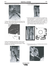
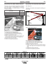
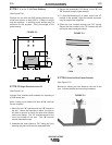
21. Adjust the length of the cables and hoses coming
out of the front of the arm to permit connections to
the feeder.
22. Secure the cables and hoses to the K1779-9 feed-
er support by tightening the hose clamp around
the 1' (0.3m) long hose.
Before tightening the hose clamp, make sure that
the 4" (102 mm) PVC tube is around the gas hose
where the clamp secures the assembly. This will
prevent any restriction in the gas flow.
------------------------------------------------------------------------
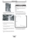
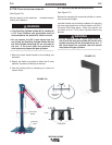
23. Secure the 3' (0.9m) long hose assembled in step
14 to the cable assemble where it exits the rear of
the arm.
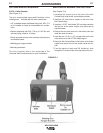
24. After installing K1779-11 Mini Console, verify
proper connections to the electrical outlet (neutral,
hot and ground circuits) by using a plug-in circuit
tester.
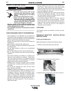
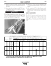
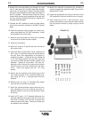
WELD CABLE SIZES
See Table A.1 for recommended copper cable sizes,
currents and duty cycles. Lengths provided are the
distance from the welder to work and back to the
welder again. Cable sizes are increased for greater
lengths primarily for the purpose of minimizing cable
drop.
TABLE A.1
CAUTION