


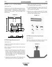
A-5
INSTALLATION
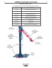
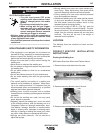
WELDING ARMS
A-5
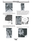
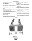
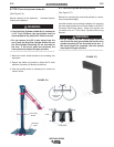
ADJUSTING FOR WIRE FEEDER WEIGHT
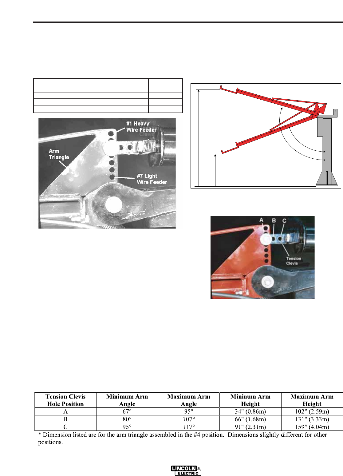
The holes in the arm triangle compensate for different
wire feeder weights. The top position, #1 is used for
heavy wire feeders. The bottom position, #7 is used
for light wire feeders.
Wire Feeder Arm triangle
hole position
LF-72 #5
LN-10, Power Feed 10, Power Feed 10M #4
DH-10, Power Feed 10 Dual, Power Feed 10M Dual #3
To change the arm triangle position:
1. Turn off power at the welding power source.
2. Support the welding arm with a fork lift or hoist.
3. Remove the tension clevis bolt.
4. Raise or lower the arm until the desired tension cle-
vis hole aligns with the desired arm triangle hole.
5. Replace the tension clevis bolt.
6. Remove the supporting equipment.
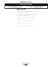
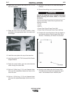
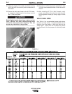
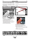
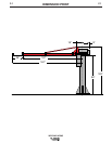
ADJUSTING THE WELDING ARM TRAVEL
(See Table A.2)
The holes in the tension clevis adjust the welding arm
travel range.
Most people prefer position A.
To change the tension clevis position:
7. Turn off power at the welding power source.
8. Support the weld arm with a fork lift or hoist.
9. Remove the tension clevis bolt.
10. Raise or lower the arm until the desired tension
clevis hole aligns with the desired arm triangle
hole.
11. Replace the tension clevis bolt.
12. Remove the supporting equipment.
Minimum
Arm Height
Maximum
Arm Height
Minimum
Arm Angle
Maximum
Arm Angle
TABLE A.2