


C-2
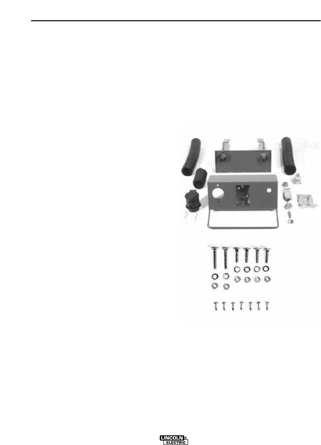
ACCESSORIES
C-2
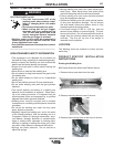
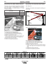
8. Extend the hose and cable(s) out through the right
front 2" tube about 32" and then feed them through
one of the 15" long black 2" hoses. Feed the cables
and black tube through the right tube of the back of
the mini console. The back cover should be facing
forward with the two pipes extending to the rear and
the two mounting brackets facing up towards the
universal feeder support.
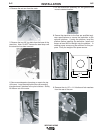
9. Connect the 3/8" braided air hose and gear clamp
to the hose connector mounted on the Mini Console
Body.
10. Feed the electrical cable through the romex con-
nector and attach the 120 VAC receptacle. Install
the receptacle and cover plate.
11. Install a quick disconnect air fitting (not included)
to the front of the short anchor coupler.
12. Verify all connections.
13. Slip the 5" piece of 2" spiral hose over the rear of
the vacuum inlet.
14. Install the Mini Console Rear Cover, making sure
the 5" long, 2" spiral hose slips over the left pipe of
the rear cover and compresses as the panel is
screwed into place. Install the two top outside #8
x 1/2" self drilling screws first and then pivot the
rear cover to allow the three bottom screws to be
installed. Tighten all five screws. Drill two 1/8"
diameter holes through the prepunched bottom
outside holes in the mini console into the back
cover. Install and tighten two #8 - 1/2" long
screws.
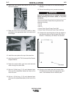
15. Secure the two brackets of the back cover to the
four mounting holes in the universal feeder sup-
port using 1/4"-20 x 1" carriage bolts and lock
washers.
16. Slide the two 15" long x 2" diameter black hoses
over the rear of the back cover pipes.
17. Install the universal feeder support and mini con-
sole assembly to the arm making sure both 2"
diameter hoses fit over the outer structural tubes
of the arm.
18. Install a 20" long x 1-1/2" diameter hose over the
electrical cable and air hose at the rear of the arm
and slide it halfway into the tube to protect the
cable and hose from wear. Secure the hose with
an adhesive (not included.)
19. Make final electrical connections by installing a
plug to the end of the electrical cable. Plug into an
approved GFI outlet.
20. Install the appropriate air fitting to the end of the
3/8" braided air hose and connect to an air supply.
21. After installing K1779-11 Mini Console, verify
proper connections to the electrical outlet (neutral,
hot and ground circuits) by using a plug-in circuit
tester.
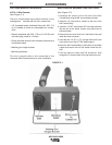
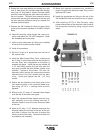
WELDING ARMS
FIGURE C.2