


A-3
INSTALLATION
POWER WAVE® i400
A-3
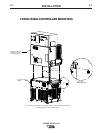
LOCATION AND MOUNTING
The POWER WAVE® i400 case is designed to sup-
port the Fanuc R30iA controller and op box (up to
300lbs), matching the controllerʼs footprint and styling.
Mounting is externally accessible for simplified inte-
gration. The flexibility of the POWER WAVE® i400
also allows it to be operated as a stand alone unit. In
either case, bolting the unit to the floor or a suitable
platform is recommended to provide maximum stabili-
ty.The minimum recommended clearance for chassis
removal is 26” (66cm) from the rear of the machine as
viewed from the output studs. See the Chassis
Removal Procedure for additional information.
• DO NOT MOUNT OVER COMBUSTIBLE SURFACES.
Where there is a combustible surface directly
under stationary or fixed electrical equipment,
that surface shall be covered with a steel plate at
least .06”(1.6mm) thick, which shall extend not
less than 5.90”(150mm) beyond the equipment
on all sides.
-----------------------------------------------------------------------
ENVIRONMENTAL CONSIDERATIONS
The POWER WAVE® i400 will operate in harsh envi-
ronments. Even so, it is important that simple preven-
tative measures are followed in order to assure long
life and reliable operation.
• The POWER WAVE® i400 must be located where
there is free circulation of clean air such that air
movement in the louvered sections of the machine
will not be restricted.
SAFETY PRECAUTIONS
Read this entire installation section before you
start installation.
ELECTRIC SHOCK can kill.
• Only qualified personnel should per-
form this installation.
• Turn the input power OFF at the dis-
connect switch or fuse box before
working on this equipment. Turn off
the input power to any other equip-
ment connected to the welding sys-
tem at the disconnect switch or fuse
box before working on the equip-
ment.
• Do not touch electrically hot parts.
• Always connect the POWER WAVE® grounding
lug (located inside the reconnect input access
door) to a proper safety (Earth) ground.
-------------------------------------------------------------
WARNING
CAUTION
• Dirt and dust that can be drawn into the POWER
WAVE® i400 should be kept to a minimum. The
use of air filters on the air intake is not recommend-
ed because normal air flow may be restricted.
Failure to observe these precautions can result in
excessive operating temperatures and nuisance
shutdown.
• Do not use the POWER WAVE® i400 in an outdoor
environment. The power source should not be sub-
jected to falling water, nor should any parts of it be
submerged in water. Doing so may cause improper
operation as well as pose a safety hazard. The
best practice is to keep the machine in a dry, shel-
tered area.
LIFTING
• Lift only with equipment of ade-
quate lifting capacity.
• Be sure machine is stable when
lifting.
• Do not lift this machine using lift
bail if it is equipped with a heavy
accessory such as trailer or gas
cylinder.
FALLING • Do not lift machine if lift bail is
EQUIPMENT can damaged.
cause injury. • Do not operate machine while
suspended from lift bail.
-----------------------------------------------------------------------
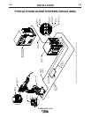
POWER WAVE® i400:
Lift the machine by the cor-
ner mounted lift bails only. Do not attempt to lift the
POWER WAVE® i400 with accessories attached to
it.
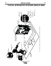
POWER WAVE® i400 with the Fanuc R30iA
Controller: When properly mounted the complete
integrated unit (power source and controller) can be
lifted using the lift hooks provided on the Fanuc
R30iA controller. Consult the Fanuc instruction manu-
al for details and precautions.
NOTE: The POWER WAVE® i400 external corner
mounted lift bales must be removed when
mounted to the Fanuc R30iA controller.
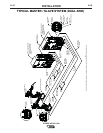
POWER WAVE® i400 Replacement Chassis:
Lift
the chassis by the lift bail on top of the harmonic filter
assembly.
STACKING
The POWER WAVE® i400 cannot be stacked.
WARNING