


A-16
INSTALLATION
POWER WAVE® i400
A-16
CONTROL CABLE CONNECTIONS
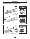
General Guidelines
Genuine Lincoln control cables should be used at all
times (except where noted otherwise). Lincoln cables
are specifically designed for the communication and
power needs of the POWER WAVE® / Power Feed sys-
tems. Most are designed to be connected end to end for
ease of extension. Generally, it is recommended that the
total length not exceed 100 ft. (30.5 m). The use of non-
standard cables, especially in lengths greater than 25 ft.
(7.6 m), can lead to communication problems (system
shutdowns), poor motor acceleration (poor arc starting),
and low wire driving force (wire feeding problems).
Always use the shortest length of control cable possible,
and DO NOT coil excess cable.
Regarding cable placement, best results will be
obtained when control cables are routed separate
from the weld cables. This minimizes the possibility
of interference between the high currents flowing
through the weld cables, and the low level signals in
the control cables. These recommendations apply to
all communication cables including ArcLink® and
Ethernet connections.
------------------------------------------------------------------------
COMMON EQUIPMENT CONNECTIONS
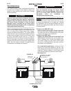
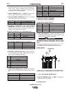
Connection Between Power Source and Wire Feeder
(K1785 or K2709 Control Cable)
The 14 pin wire feeder control cable connects the power
source to the wire drive. It contains all of the necessary
signals to drive the motor and monitor the arc, including
the motor power, tachometer, and arc voltage feedback
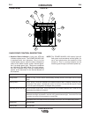
signals. The wire feeder connection on the POWER
WAVE® i400 is located on the recessed control panel
above the output studs. Fanuc robot arms are equipped
with internal cabling and provide a standard 14 pin MS-
style connection at the base of the robot, and near the
wire feeder mount at the top of the arm. The K2709
series external dress cable is recommended for severe
duty applications such as hard automation or for robot
arms not equipped with an internal control cable. Best
results will be obtained when control cables are routed
separate from the weld cables, especially in long dis-
tance applications. Maximum cable length should not
exceed 100ft(30.5m).
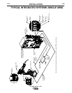
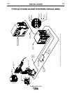
Connection Between Power Source and ArcLink®XT
Compatible Controllers or Ethernet Networks. Newer
model controllers, such as the Fanuc R30iA, communicate
via ArcLink®XT over an industrial Ethernet connection. To
facilitate this, the Power Wave i400 is equipped with an IP67
rated ODVA compliant RJ-45 Ethernet connector, which is
located on the recessed control panel above the output
studs. A special access chute is provided above the
Ethernet connection on the Power Wave i400 to accommo-
date seamless integration with the Fanuc R30iA controller.
The K2677-1 Integration Kit includes a specially designed
industrial rated Ethernet cable for this purpose.
It is highly recommended that all external Ethernet equip-
ment (cables, switches, etc.), as defined by the connection
diagrams, be obtained through the Lincoln Electric
Automation Division. It is critical that all Ethernet cables
external to either a conduit or an enclosure are solid con-
ductor, shielded cat 5e cable, with a drain. The drain should
be grounded at the source of transmission, such as a net-
work switch or the Fanuc R30iA ground strip. Ethernet
cables will achieve optimal performance levels at distances
up to 25 feet. Special attention to layout may be required to
support distances greater than 25 feet, including specialized
network equipment. For best results, always route Ethernet
cables away from weld cables, wire drive control cables, or
any other current carrying device that can create a fluctuat-
ing magnetic field. For additional guidelines refer to industry
standard documents for industrial Ethernet networks. Failure
to follow these recommendations can result in an Ethernet
connection failure during welding.
The ethernet port of the Power Wave i400 is factory config-
ured with a dynamic IP address. This is required for seam-
less operation with the Fanuc R30iA controller.
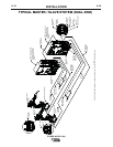
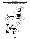
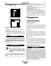
Connection Between Power Source and ArcLink®
Compatible Controllers (K1543 or K2683 ArcLink
Control Cable)
Earlier model Fanuc controllers communicate via traditional
ArcLink® over a standard 2 wire CAN based network. In
these systems, the 5 pin ArcLink control cable connects the
power source to the controller.
The control cable consists of two power leads, one twisted
pair for digital communication, and one lead for voltage
sensing. The sense leads and power leads are typically
unused in this application. The 5 pin ArcLink connection on
the POWER WAVE® i400 is located on the recessed control
panel above the output studs. The control cable is keyed
and polarized to prevent improper connection. Best results
will be obtained when control cables are routed separate
from the weld cables, especially in long distance applica-
tions. The recommended combined length of the ArcLink
control cable network should not exceed 200ft(61.0m).
CAUTION