


D-2
MAINTENANCE
D-2
POWER WAVE® i400
FIGURE D.1a
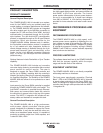
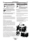
4. Remove the left case side by pulling out from the
bottom.
5. Disconnect the chassis input power leads (1E, 2E &
3E) from terminal block “3TB” located in the cabinet
reconnect area, and remove the chassis ground
from the stud located in front the terminal block.
6. Carefully slide the chassis from the cabinet by
pulling on the fan bracket. (see “Location and
Mounting” section of this document for instructions
on lifting the chassis).
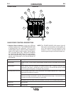
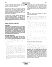
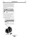
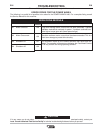
CAPACITOR DISCHARGE PROCEDURE
• Prior to transporting or servicing
chassis it is important to verify the
capacitors are completely dis-
charged.
------------------------------------------------------------------------
1. Use a DC voltmeter to check that NO voltage is
present across the terminals of both capacitors.
Note: Presence of capacitors voltage is also indi-
cated by LEDʼs (See figure D.1a)
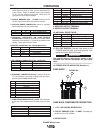
2. If voltage is present wait for capacitors to complete-
ly discharge (this may take several minutes) or dis-
charge the capacitors as follows:
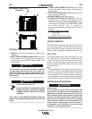
• Obtain a power resistor (25 ohms, 25 watts).
• Hold resistor body with electrically insulated
glove. DO NOT TOUCH TERMINALS.
CAPACITOR VOLTAGE MAY EXCEED
400VDC.Connect the resistor terminals
across the two studs in the position shown.
Hold in each position for 10 second. Repeat
for both capacitors.
• Use a DC voltmeter to check that voltage is
not present across the terminals of both
capacitors.
CAPACITOR
TERMINALS
RESISTOR
CAPACITOR CHARGE
INDICATORS (LED’S)
CAUTION