


GENERAL GUIDELINES
• Select the appropriate size cables per the
“Output Cable Guidelines” in Table A.1.
Excessive voltage drops caused by undersized
welding cables and poor connections often result in
unsatisfactory welding performance. Always use the
largest welding cables (electrode and work) that are
practical, and be sure all connections are clean and
tight.
Note: Excessive heat in the weld circuit indicates
undersized cables and/or bad connections.
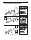
• Route all cables directly to the work and wire
feeder, avoid excessive lengths and do not coil
excess cable. Route the electrode and work cables
in close proximity to one another to minimize the
loop area and therefore the inductance of the weld
circuit.
• Always weld in a direction away from the work
(ground) connection.
In Table A.1 are copper cable sizes recommended for
different currents and duty cycles. Lengths stipulated
are the distance from the welder to work and back to
the welder again. Cable sizes are increased for
greater lengths primarily for the purpose of minimizing
cable drop.
A-12
INSTALLATION
POWER WAVE® i400
A-12
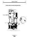
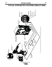
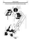
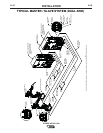
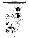
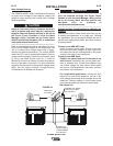
ELECTRODE AND WORK CONNECTIONS
Connect the electrode and work cables between the
appropriate output studs of the POWER WAVE® i400
and the robot weld cell per the connection diagrams
included in this document. Size and route the cables
per the following.
• Most welding applications run with the electrode
being positive (+). For those applications, connect
the electrode cable between the wire drive feed plate
and the positive (+) output stud on the power source.
Connect a work lead from the negative (-) power
source output stud to the work piece.
• When negative electrode polarity is required, such
as in some Innershield applications, reverse the out-
put connections at the power source (electrode cable
to the negative (-) stud, and work cable to the posi-
tive (+) stud).
Negative electrode polarity operation WITHOUT
use of a remote work sense lead (21) requires the
Negative Electrode Polarity attribute to be set. See
the Remote Sense Lead Specification section of
this document for further details.
For additional Safety information regarding the elec-
trode and work cable set-up, See the standard “SAFE-
TY INFORMATION” located in the front of this
Instruction Manual.
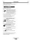
CAUTION
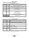
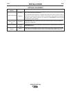
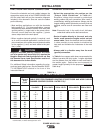
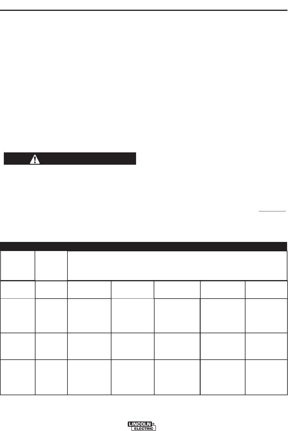
OUTPUT CABLE GUIDELINES
TABLE A.1
CABLE SIZES FOR COMBINED LENGTHS OF ELECTRODE AND WORK CABLES
(RUBBER COVERED COPPER - RATED 75°C)**
Percent
Duty
Cycle
60
100
20
40 & 30
30
40
60
100
60
100
60
60
100
60
2
2
4 or 5
3
3
2
1
1
1
2/0
1/0
2/0
3/0
2/0
2
2
3
3
3
2
1
1
1
2/0
1/0
2/0
3/0
2/0
2
2
2
2
2
1
1
1
1
2/0
2/0
2/0
3/0
3/0
1
1
1
1
1
1
1
1
1/0
2/0
2/0
3/0
3/0
3/0
1/0
1/0
1/0
1/0
1/0
1/0
1/0
1/0
2/0
3/0
3/0
4/0
4/0
4/0
200
200
225
225
250
250
250
250
300
325
350
400
400
500
Amperes
0 to 50 Ft. 50 to 100 Ft. 100 to 150 Ft. 150 to 200 Ft. 200 to 250 Ft.
** Tabled values are for operation at ambient temperatures of 40°C and below. Applications above 40°C may require cables larger than
recommended, or cables rated higher than 75°C.