


B-5
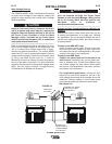
OPERATION
B-5
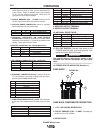
POWER WAVE® i400
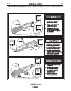
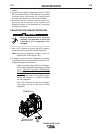
2. THERMAL INDICATOR (THERMAL OVERLOAD): A
yellow light that comes on when an over temperature sit-
uation occurs. Output is disabled and the fan continues
to run, until the machine cools down. When cool, the
light goes out and output is enabled.
3. CIRCUIT BREAKER (CB1 - 15 AMP): Protects the 40
volt DC supply for the feeder and machine controls.
4. VOLTAGE SENSE CONNECTOR: Allows for separate
remote electrode and work sense leads.
Pin Leads Function
3 21 Work Voltage Sense
1 67C Electrode Voltage Sense
5. OPTIONAL DEVICENET OR SYNC-TANDEM
CONNECTOR: Available as optional kits to support either
DeviceNet communication, or synchronized tandem pulse
welding. These options cannot coexist.
DEVICENET CONNECTOR (5 PIN - SEALED MINI STYLE):
Pin Lead Function
2 894 +24 VDC DeviceNet
3 893 Common DeviceNet
4 892 DeviceNet H
5 891 DeviceNet L
SYNC-TANDEM CONNECTOR (4 PIN – MS STYLE):
Pin Lead Function
A White “Ready” H
B Black/White “Ready” L
C Green “Kill” H
D Black/Green “Kill” L
6. ETHERNET CONNECTOR (RJ-45): Used for ArcLink
®
XT communication. Also used for diagnostics and repro-
gramming the POWER WAVE® i400.
Pin Function
1 Transmit +
2 Transmit -
3 Receive +
4 ---
5 ---
6 Receive -
7 ---
8 ---
7. WIRE FEEDER RECEPTACLE (14-PIN): For connection
to the Auto Drive 4R90 and Power Feed 10R wire feed-
ers.
Pin Leads Function
A 539 Motor +
B 541 Motor -
C 521 Solenoid +
D 522 Solenoid Common
E 845 Tach 2A differential signal
F 847 Single Tach input
G 841 +15V Tach supply
H 844 Tach common
I Open Reserved for future use
J GND-A Shielding drain
K 842 Tach 1A differential signal
L 843 Tach 1B differential signal
M 846 Tach 2B differential signal
N 67A / 67B Electrode Voltage Sense
8. NEGATIVE OUTPUT TERMINAL
9. POSITIVE OUTPUT TERMINAL
10. ARCLINK
®
RECEPTACLE:
Pin Leads Function
A 153A / 153B Communication Bus L
B 154A / 154B Communication Bus H
C 67B / 67C Electrode Voltage Sense
D 52 / 52A +40V DC
E 51 / 51A 0 VDC
11. ON / OFF SWITCH: Controls input power to the
POWER WAVE® i400, and when properly inte-
grated, the Fanuc R30iA Controller.
The POWER WAVE® i400 ON/OFF switch is NOT
intended as a Service Disconnect for this equip-
ment.
------------------------------------------------------------------------
12. FEEDER STATUS INDICATOR (See Item 1)
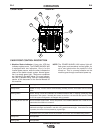
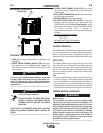
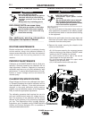
CASE BACK COMPONENTS DESCRIPTION
1. 115V / 15A DUPLEX RECEPTACLE
2. CIRCUIT BREAKER (CB2 - 15 AMP): Provides pro-
tection for the 115V auxiliary.
3. RATING PLATE
1
2
3
CASE BACK
FIGURE B.2
WARNING