


A-7
INSTALLATION
POWER WAVE® R350
A-7
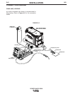
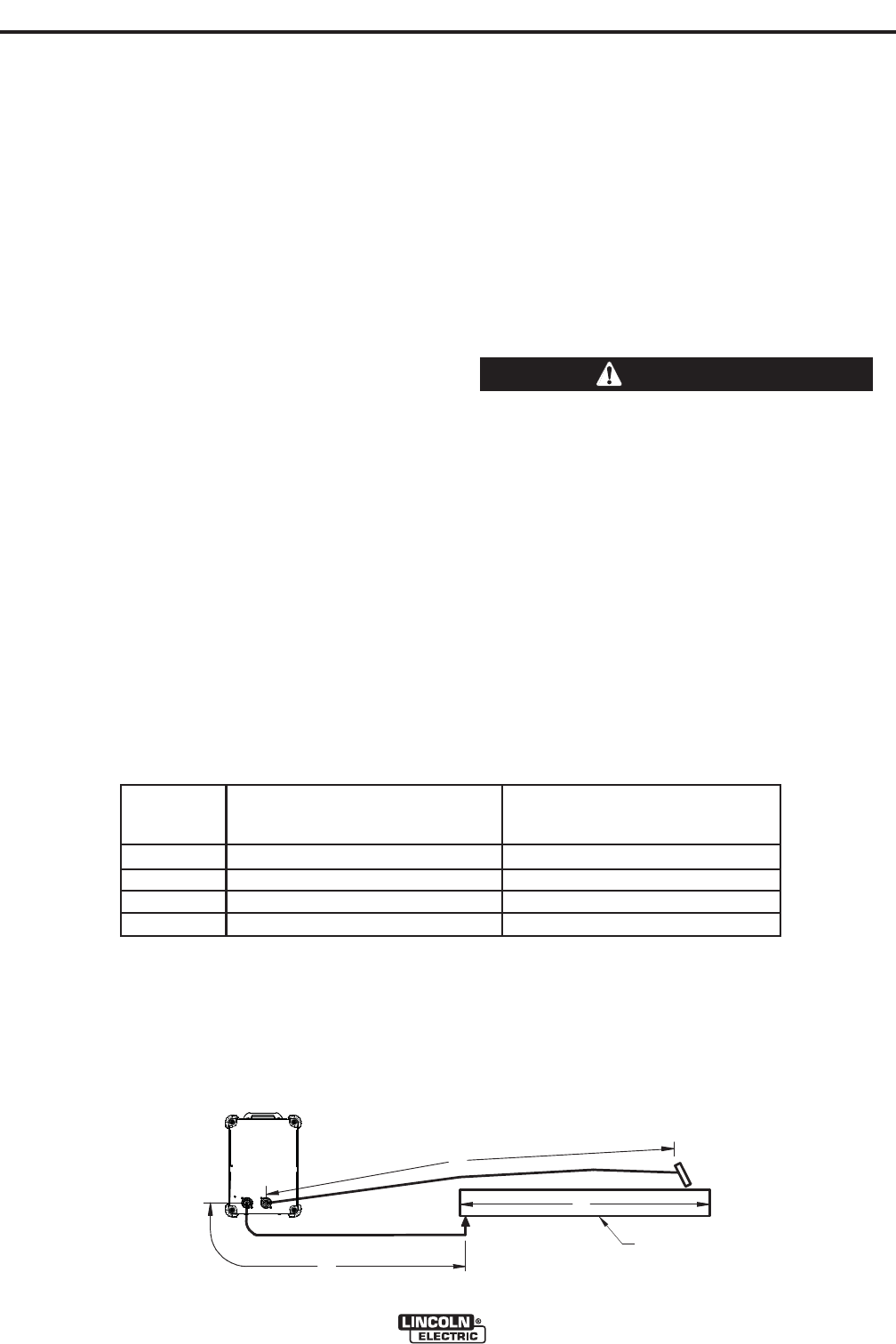
FIGURE A.6
B
A
C
WORK
POWER
WAVE
R350
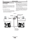
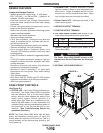
CABLE INDUCTANCE AND ITS
EFFECTS ON WELDING
Excessive cable inductance will cause the welding
performance to degrade. There are several factors
that contribute to the overall inductance of the cabling
system including cable size, and loop area. The loop
area is defined by the separation distance between
the electrode and work cables, and the overall welding
loop length. The welding loop length is defined as the
total of length of the electrode cable (A) + work cable
(B) + work path (C) (See Figure A.6).
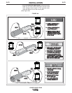
To minimize inductance always use the appropriate
size cables, and whenever possible, run the electrode
and work cables in close proximity to one another to
minimize the loop area. Since the most significant fac-
tor in cable inductance is the welding loop length,
avoid excessive lengths and do not coil excess cable.
For long work piece lengths, a sliding ground should
be considered to keep the total welding loop length as
short as possible.
REMOTE SENSE LEAD
SPECIFICATIONS
Voltage Sensing Overview
The best arc performance occurs when the POWER
WAVE R350 has accurate data about the arc condi-
tions.
Depending upon the process, inductance within the
electrode and work cables can influence the voltage
apparent at the studs of the welder, and have a dra-
matic effect on performance. Remote voltage sense
leads are used to improve the accuracy of the arc volt-
age information supplied to the control pc board.
Sense Lead Kits (K940-xx) are available for this pur-
pose.
The POWER WAVE R350 has the ability to automati-
cally sense when remote sense leads are connected.
With this feature there are no requirements for setting-
up the machine to use remote sense leads. This fea-
ture can be disabled through the Diagnostics Utility
(available at www.powerwavesoftware.com).
If the auto sense lead feature is disabled and
remote voltage sensing is enabled but the sense
leads are missing, improperly connected extreme-
ly high welding outputs may occur.
------------------------------------------------------------------------
General Guidelines for Voltage Sense Leads
Sense leads should be attached as close to the weld
as practical, and out of the weld current path when
possible. In extremely sensitive applications it may be
necessary to route cables that contain the sense
leads away from the electrode and work welding
cables.
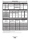
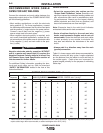
Voltage sense leads requirements are based on the
weld process (See Table A.2)
CAUTION
Process
GMAW
GMAW-P
FCAW
GTAW
Electrode Voltage Sensing
(1)
67 lead
67 lead required
67 lead required
67 lead required
Voltage sense at studs
Work Voltage Sensing
(2)
21 lead
21 lead optional
(3)
21 lead optional
(3)
21 lead optional
(3)
Voltage sense at studs
TABLE A.2
(1)
The electrode voltage sense lead (67) is automatically enabled by the weld process, and integral to the 5 pin arclink control cable (K1543-
xx).
(2)
When a work voltage sense lead (21) is connected the power source will automatically switch over to using this feedback.
(3)
Negative polarity semi-automatic process operation WITHOUT use of a remote work sense lead (21) requires the Negative Electrode
Polarity attribute to be set.