


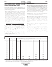
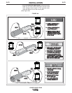
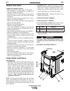

6. VOLTAGE SENSE CONNECTOR: Allows for sep-
arate remote electrode and work sense leads.
Pin Lead Function
3 21 Work Voltage Sense
1 67E Electrode Voltage Sense
7. ON/OFF SWITCH: Controls input power to the
Power Wave R350.
The Power Wave R350 ON/OFF switch is NOT
intended as a Service Disconnect for this equip-
ment.
------------------------------------------------------------------------
8. OPTIONAL VOLTS/AMPS DISPLAY
B-3
OPERATION
B-3
DESIGN FEATURES
Loaded with Standard Features
• Multiple process DC output range: 5 - 350 Amps.
• 200 – 600 VAC, 1 for 208 and 230, 3 phase for all
voltages, 50-60Hz input power.
• New and Improved Line Voltage Compensation
holds the output constant over wide input voltage
fluctuations.
• Utilizes next generation microprocessor control,
based on the ArcLink® platform.
• State of the art power electronics technology yields
superior welding capability.
• Electronic over current protection.
• Input over voltage protection.
• F.A.N. (fan as needed). Cooling fan runs when the
output is energized and for 5 minutes after the out-
put has been turned off.
• Thermostatically protected for safety and reliability.
• Ethernet connectivity via RJ-45 connector.
• Panel mounted Status, FeedHead Status, and
Thermal LED indicators facilitate quick and easy
troubleshooting.
• Potted PC boards for enhanced ruggedness/reliabil-
ity.
• 115V/15A duplex receptacle supports rigorous
demands of heavy duty fume extraction and water
cooling equipment.
• Enclosure reinforced with heavy duty aluminum
extrusions for mechanical toughness.
• Waveform Control Technology™ for good weld
appearance and low spatter, even when welding
nickel alloys.
• Sync Tandem installed.
• Auto Drive 4R9100, 4R200 and PF-10R feeders
supported via standard 14 pin MS style connector.
• Cam Lock type connectors.
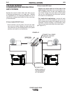
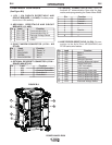
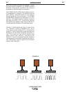
CASE FRONT CONTROLS
(See Figure B.1)
1. STATUS LED - A two color LED that indicates sys-
tem errors. The Power Wave R350 is equipped
with two indicators. One is for the inverter power
source, while the other indicates the status of the
feeder control system. Normal operation is a
steady green light. Basic error conditions are indi-
cated in the table below. For more information and
a detailed listing, see the troubleshooting section of
this document or the Service Manual for this
machine. (See Troubleshooting Section for
operational functions.)
NOTE: The Power Wave R350 status light will flash
green, and sometimes red and green, for up to one
minute when the machine is first turned on. This is a
normal situation as the machine goes through a self
test at power up.
POWER WAVE® R350
2. THERMAL LED - (Thermal overload): A yellow
light that comes on when an over temperature situ-
ation occurs. Output is disabled and the fan con-
tinues to run, until the machine cools down. When
cool, the light goes out and output is enabled.
3. Feeder Status LED - Indicates the status of the
feeder control system.
4. NEGATIVE OUTPUT TERMINAL.
5. POSITIVE OUTPUT TERMINAL.
8
1
2
4
7
5
6
3
FIGURE B.1
WARNING