


A-11
INSTALLATION
POWER WAVE® R350
A-11
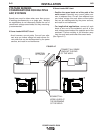
CONTROL CABLE CONNECTIONS
General Guidelines
Genuine Lincoln control cables should be used at all
times (except where noted otherwise). Lincoln cables
are specifically designed for the communication and
power needs of the Power Wave / Power Feed sys-
tems. Most are designed to be connected end to end
for ease of extension. Generally, it is recommended
that the total length not exceed 100ft. (30.5m). The
use of non-standard cables, especially in lengths
greater than 25 feet, can lead to communication prob-
lems (system shutdowns), poor motor acceleration
(poor arc starting), and low wire driving force (wire
feeding problems). Always use the shortest length of
control cable possible, and DO NOT coil excess
cable.
Regarding cable placement, best results will be
obtained when control cables are routed separate
from the weld cables. This minimizes the possibility of
interference between the high currents flowing
through the weld cables, and the low level signals in
the control cables. These recommendations apply to
all communication cables including ArcLink® and
Ethernet connections.
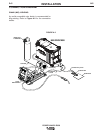
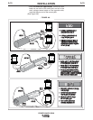
Product specific Installation Instructions
Connection Between Power Source and ArcLink®
Compatible Wirefeeders (K1543-xx, K2683-xx –
ArcLink Control Cable)
The 5-pin ArcLink control cable connects the power
source to the wire feeder. The control cable consists
of two power leads, one twisted pair for digital com-
munication, and one lead for voltage sensing. The 5-
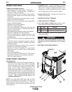
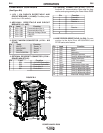
pin ArcLink connection on the POWER WAVE R350 is
located on the rear panel above the power cord. The
control cable is keyed and polarized to prevent
improper connection. Best results will be obtained
when control cables are routed separate from the
weld cables, especially in long distance applications.
The recommended combined length of the ArcLink
control cable network should not exceed 200ft.
(61.0m).
Connection Between Power Source and Wire
Feeder (K1785 or K2709 Control Cable)
The 14-pin wire feeder control cable connects the
power source to the wire drive. It contains all of the
necessary signals to drive the motor and monitor the
arc, including the motor power, tachometer, and arc
voltage feedback signals. The wire feeder connection
on the POWER WAVE R350 is located in the upper-
right corner of the case back. The K2709 series exter-
nal dress cable is recommended for severe duty appli-
cations such as hard automation or for robot arms not
equipped with an internal control cable. Best results
will be obtained when control cables are routed sepa-
rate from the weld cables, especially in long distance
applications. Maximum cable length should not
exceed 25ft (7.6m).
Connection Between Power Source and Ethernet
Networks
The POWER WAVE R350 is equipped with an IP67
rated ODVA compliant RJ-45 Ethernet connector,
which is located on the rear panel. All external
Ethernet equipment (cables, switches, etc.), as
defined by the connection diagrams, must be supplied
by the customer. It is critical that all Ethernet cables
external to either a conduit or an enclosure are solid
conductor, shielded cat 5e cable, with a drain. The
drain should be grounded at the source of transmis-
sion. For best results, route Ethernet cables away
from weld cables, wire drive control cables, or any
other current carrying device that can create a fluctu-
ating magnetic field. For additional guidelines refer to
ISO/IEC 11801. Failure to follow these recommenda-
tions can result in an Ethernet connection failure dur-
ing welding.
Selecting a Wire Drive and Setting the Wire Drive
Gear Ratio.
The POWER WAVE R350 can accommodate a num-
ber of standard wire drives including the AutoDrive
4R100 (default), AutoDrive 4R220, and PF-10R. The
feeder control system must be configured for both the
wire drive type and gear ratio (high or low speed
range). This can be accomplished with the Weld
Manager Utility (included on the Power Wave
Utilities and Service Navigator CDʼs or available at
www.powerwavesoftware.com).
Additional information is also available in the “How To”
section at www.powerwavesoftware.com.