


Return to Section TOC Return to Section TOC Return to Section TOC Return to Section TOC
Return to Master TOC Return to Master TOC Return to Master TOC Return to Master TOC
A-5
INSTALLATION
WIRE-MATIC 255
A-5
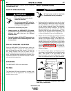
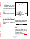
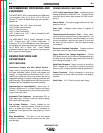
7. Attach the flow regulator to the cylinder valve and
tighten the union nut(s) securely with a wrench.
a. NOTE: If connecting the flow regulator to
100% CO2 cylinder, insert the regulator
adapter between the regulator and cylinder
valve. If adapter is equipped with a plastic
washer, be sure it is seated properly to con-
nect to the CO2 cylinder.
8. Connect one end of the inlet gas hose to the outlet
fitting of the flow regulator.
9. Connect the other end of the inlet gas hose to the
WIRE-MATIC 255 rear fitting.
10. Tighten both the union nuts securely with a
wrench.
11. Before opening the cylinder valve, turn the regula-
tor adjusting knob counter-clockwise until the pres-
sure is released from the adjusting spring.
12. Open the cylinder valve slowly a fraction of a turn.
a. When the cylinder pressure gage pointer stops
moving, open the valve fully.
NEVER STAND DIRECTLY IN FRONT OF OR
BEHIND THE FLOW REGULATOR WHEN OPENING
THE CYLINDER VALVE. ALWAYS STAND TO ONE
SIDE.
13. The flow regulator is adjustable. Adjust the flow
regulator for the flow rate recommended for the
procedure and process being used before making
the weld.
FIGURE A.4 - Input Gas Supply Connections
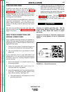
RECONNECT PROCEDURE
Multiple voltage machines are shipped connected to
the highest input voltage listed on the machine's rating
plate. Before installing the machine, check that the
Reconnect Panel in the Input Box Assembly is con-
nected for the proper voltage.
Failure to follow these instructions can cause
immediate failure of components within the
machine.
___________________________________
To reconnect a dual or triple voltage machine to a dif-
ferent voltage, change the position of the leads or links
on the Reconnect Panel based on the type of
machine. Follow The Input Supply Connection
Diagram located on the inside of the Case Back
Reconnect Panel Access Door.
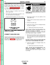
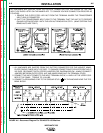
For 208/230/1/60 machine(s), see Figure A.5.
For 230/460/575/1/60 machine(s), see Figure A.6.
CAUTION