


Return to Section TOC Return to Section TOC Return to Section TOC Return to Section TOC
Return to Master TOC Return to Master TOC Return to Master TOC Return to Master TOC
ACTIVE SCR RECTIFIER ASSEMBLY TEST (CONTINUED)
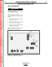
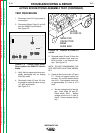
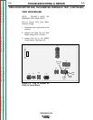
7. Connect the Tester to the SCR 1 as
shown in Figure F.7.
a. Connect Tester lead (A) to the
anode.
b. Connect Tester lead (C) to the
cathode.
c. Connect Tester lead (G) to the
gate.
FIGURE F.7 - SCR Tester Circuit and
SCR connections.
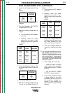
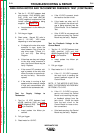
8. Close switch SW-1.
NOTE: Switch SW-2 should be open.
9. Read meter for zero voltage.
a. If the voltage reading is higher
than zero, the SCR is shorted.
10. Close or keep closed switch SW-1.
11. Close switch SW-2 for 2 seconds
and release and read meter.
a. If the voltage is 3 - 6 volts while
the switch is closed and after
the switch is open, the SCR is
functioning.
b. If the voltages is 3-6 volts only
when the switch is closed or
there is no voltage when the
switch is closed, the SCR is
defective.
NOTE: Be sure battery is functioning
properly. A low battery can affect the
results of the test. Repeat Battery Test
Procedure in Step 6 if needed.
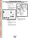
12. Open switch SW-1.
13. Reconnect the Tester leads. See
Figure F.7.
a. Connect Tester lead (A) to the
cathode.
b. Connect Tester lead (C) to the
anode.
c. Disconnect Test lead (G) from
the gate.
14. Close switch SW-1.
15. Read meter for zero voltage.
a. If the voltage is zero, the SCR is
functioning.
b. If the voltage is higher than
zero, the SCR is shorted.
16. Perform the Active Test Procedure
outlined in Steps 5-13 for SCR 2.
17. Replace all SCR assemblies that do
not pass the above tests.
18. Replace all Molex Plugs onto the
Control Board and connect leads X2
and X3.
F-18
TROUBLESHOOTING & REPAIR
F-18
WIRE-MATIC 255