


Return to Section TOC Return to Section TOC Return to Section TOC Return to Section TOC
Return to Master TOC Return to Master TOC Return to Master TOC Return to Master TOC
F-24
TROUBLESHOOTING & REPAIR
F-24
WIRE-MATIC 255
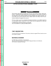
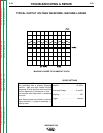
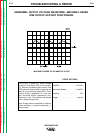
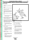
This is NOT a typical DC output voltage
waveform. One output SCR is not function-
ing. Note the increased ripple content. One
SCR gate was disconnected to simulate an
open or non-functioning output SCR. Each
vertical division represents 20 volts and
each horizontal division represents 5 mil-
liseconds in time. The machine was loaded
with a resistance grid bank.
Note: Scope probes connected at machine
output terminals: (+) probe to electrode, (-)
probe to work.
Volts/Div . . . . . . . . . . . . . . . . .20 V/Div.
Horizontal Sweep . . . . . . . . . .5 ms/Div.
Coupling . . . . . . . . . . . . . . . . . . . . .DC.
Trigger . . . . . . . . . . . . . . . . . . .Internal.
SCOPE SETTINGS
MACHINE LOADED TO 220 AMPS AT 22 VDC
ABNORMAL OUTPUT VOLTAGE WAVEFORM - MACHINE LOADED
ONE OUTPUT SCR NOT FUNCTIONING