


Return to Section TOC Return to Section TOC Return to Section TOC Return to Section TOC
Return to Master TOC Return to Master TOC Return to Master TOC Return to Master TOC
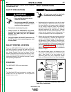
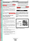
CONNECT OUTPUT COMPONENTS
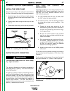
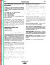
INSTALL THE WORK CLAMP
Attach the work clamp to the cable which extends from
the front of the machine using the following procedure:
1. Insert the lug on the end of the work cable through
the strain relief hole in the work clamp handle. See
Figure A.7.
2. Slide the work cable through the hole up to the bolt
and nut.
3. Fasten work cable using the bolt and nut provided.
FIGURE A.7 - Installing The Work Clamp.
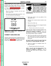
OUTPUT POLARITY CONNECTION
Turn the welder Power Switch OFF before chang-
ing output connection.
____________________________________
The welder is shipped from the factory connected for
electrode positive (+) polarity. This is the normal polar-
ity for GMA welding.
If negative (-) polarity is required, interchange the con-
nection of the electrode and work cables at the output
terminals located in the wire drive compartment near
the front panel. The electrode cable, which is attached
to the wire drive, is to be connected to the negative (-)
labeled output terminal. The work cable which is
attached to the work clamp is to be connected to the
positive (+) labeled output terminal.
A-7
INSTALLATION
WIRE-MATIC 255
A-7
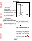
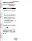
GUN LINER AND CONTACT TIP
INSTALLATION
The Magnum 250L gun and cable provided with the
WIRE-MATIC 255 is factory installed with a liner for a
.035-.045” (0.9-1.2mm) diameter electrode and an
.035” (0.9mm) contact tip.
1. If a .045” diameter wire size is to be used, install
the .045” contact tip (also provided).
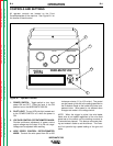
2. For other wire sizes, use the following procedure
for contact tip and gas nozzle installation. See
Figure A.8.
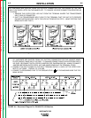
a. Choose the correct size contact tip for the
electrode being used (wire size is stenciled on
the side of the contact tip) and screw it snugly
into the gas diffuser.
b Be sure the nozzle insulator is fully screwed
onto the gun tube and does not block the gas
holes in the diffuser.
c. Slip the appropriate gas nozzle onto the noz-
zle insulator. Either a standard .50" (12.7mm)
or optional .62” (15.9mm) I.D. slip-on gas noz-
zle may be used and should be selected
based on the welding application.
d. Adjust the gas nozzle for the GMAW process
to be used.
For the short-circuiting transfer process, the contact tip
end should be flush to extended to .12" (3.2mm). See
Figure A.8.
For the spray transfer process, the contact tip should
be flush to recessed .12" (3.2mm). See Figure A.8.
FIGURE A.8 - Contact Tip and Electrode
Connections.
WARNING