


A-8
INSTALLATION
WIRE-MATIC 255
A-8
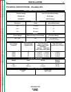
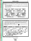
WIRE SIZE CONVERSION PARTS
The Wire-Matic 255 is rated to feed .025" through .045"
(0.6-1.2mm) solid or cored electrode sizes. For vari-
ous drive roll kits refer to
Acessories Section
.
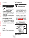
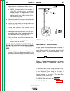
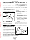
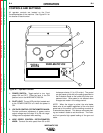
GUN AND CABLE INSTALLATION
Turn the welder Power Switch OFF before chang-
ing output connection.
____________________________________
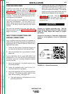
1. Lay the cable out straight.
2. Locate the knurled thumb screw on conductor
block inside wire feed compartment. Unscrew it
until the tip of the screw no longer protrudes into
gun opening as seen from front of machine.
3. Insert the brass connector on the end of the gun
cable into conductor block through opening in the
front panel. Make sure the connector is fully insert-
ed and tighten thumb screw.
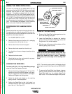
4. Connect the gun trigger connector from the gun
and cable to the mating receptacle on the front
panel. Make sure that the keyways are aligned,
insert and tighten retaining ring.
NOTE: If a gun and cable other than the Magnum
250L is used, it must conform to connector specifica-
tions and the gun trigger switch must be capable of
switching 5 milliamps at 15 volts DC -resistive.
The gun trigger switch connected to the gun trig-
ger control cable must be a normally open,
momentary switch. The terminals of the switch
must be insulated from the Welding circuit.
Improper operation of or damage to the WIRE-
MATIC 255 might result if this switch is common to
an electrical circuit other than the WIRE-MATIC 255
trigger circuit.
____________________________________
Return to Section TOC Return to Section TOC Return to Section TOC Return to Section TOC
Return to Master TOC Return to Master TOC Return to Master TOC Return to Master TOC
WARNING
CAUTION