


10
1
2
Fig.3
008744
To remove the blade guard for non through cutting
operations reverse the above steps 1 - 3.
Installation of Side Guards to Blade Guard
Assembly
WARNING:
• The guard assembly and side guards should
only be used with the riving knife/spreader in
the spreader position to prevent guard
interference with the work pieces. The use of
the guard assembly with the riving knife/spreader
in the riving knife position may cause interference
with the work piece resulting in a kickback situation
and possible serious personal injury.
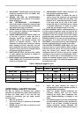
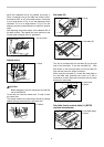
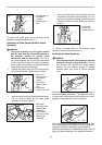
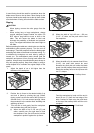
1. Release the locking lever pin of the side guard by
lifting the locking lever tab as shown in figure 1.
1
3
2
Fig.1
008745
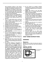
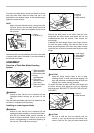
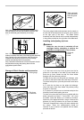
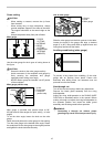
2. With the locking lever pin released position the pin
into the notch provided on the blade guard
assembly as shown in figure 2.
1
2
Fig.2
008746
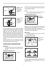
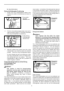
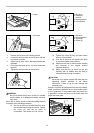
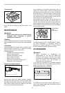
3. Once the locking lever pin is placed into the notch
provided on the blade guard assembly it is to be
locked into position by pushing the tab of the pin's
locking lever into the locked position as shown in
Figure 3.
1
Fig.3
008747
To remove the blade guard for non through cutting
operations reverse the above steps 1-3.
Antikickback Pawl Operation
WARNING:
• Use the Antikickback pawls whenever possible
during the through cutting operations. This will
help prevent the material from being pushed
forward into the operator during a kickback
situation which may result in serious personal
injury.
1
2
Fig.1
008936
1
2
Fig.2
008937
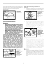
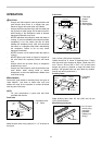
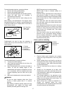
Item 1 illustrates the antikickback pawl on the right side
of the blade being lifted and placed into the pawl holder
located at the back of the blade guard assembly.In
addition item2 illustrates the antikickback pawl on the left
side of the blade remaining in the operational position.
The blade guard assembly item 1 is provided with two on
board antikickback pawls item 2. The pawls are located
on either side of the blade and can be stored or put into
operation independently for ease of operation
1. The locking
lever in the
locked position
1. The Notch
provided in the
Blade Guard
Assembly
2. Place locking
lever pin into the
blade guard
assembly
1.
Side Guard
Locking Lever in
the released
position
2.
Side Guard
Locking Lever
Tab
3.
Side Guard
Locking Lever Pin
1. Locking Lever in
the locked
position
2. Locking Lever
tab