


11
1
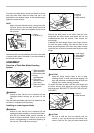
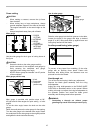
Fig.3
008938
1
2
3
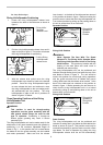
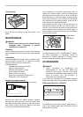
Fig.4
008939
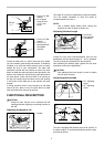
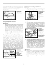
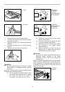
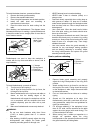
Storage of Blade Guards and Accessories
1
006152
1
2
006153
1
009010
The miter gauge, blade and wrenches can be stored on
the left side of the base and the rip fence can be stored
at the right side of the base. The Blade Guard
Assembly and Side Guards can be stored independently
in the pocket provided on the right side of the table base.
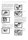
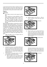
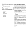
Installing and adjusting rip fence
WARNING:
• Always be sure the tool is switched off and
unplugged before attempting to perform the
installation and adjustment of the rip fence.
1
2
3
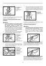
008732
1) Fit the hook on the tip of the rip fence into the far
guide rail on the table or sub table (R) and install and
push the rip fence forward so that the fence holder
engages with the nearmost guide rail.
To slide the rip fence on the guide rail sideways, pivot
the knob on the fence holder to the half way of its travel.
To secure the rip fence, pivot fully the knob on the fence
holder.
2) To slide the rip fence on the guide rail sideways,
return the knob on the fence holder fully without pulling
the lever on the knob.
3) To remove it, pull the lever on the knob and pivot the
knob fully forward while pulling the lever.
To check to be sure that the rip fence is parallel with the
blade, secure the rip fence 2 - 3 mm (5/64" - 1/8" ) from
the blade. Raise the blade up to maximum elevation.
Mark one of the blade teeth with a crayon. Measure the
distance (A) and (B) between the rip fence and blade.
Take both measurements using the tooth marked with
the crayon. These two measurements should be
identical. If the rip fence is not parallel with the blade,
proceed as follows:
1. Guide rail
2. Knob
3. Hook
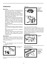
1. Table saw blade
guard assembly
and side guard
storage
1. Rip fence
2. Push stick
1. Miter gauge
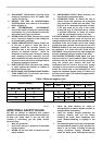
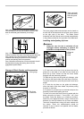
Item 1 indicates the location of the antikickback pawl
holders located at the back of the blade guard assembly
Item 2 points to the arrow direction which should be
followed when taking the pawls out of the storage
position and placing them into operation
Item 3 indicates the direction of which the pawls should
be lifted when storing and placing them into the
antikickback pawl holders
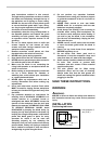
Item 1 demonstarates both antikickback pawls being
lifted and placed into the pawl holders located at the
back of the blade guard assembly for storage