


9
pop up above the table to provide an easy grasping area
on the unit so that it can be pulled up from below the
table and moved into the next desired position.
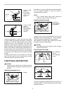
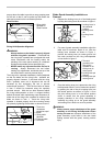
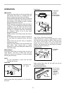
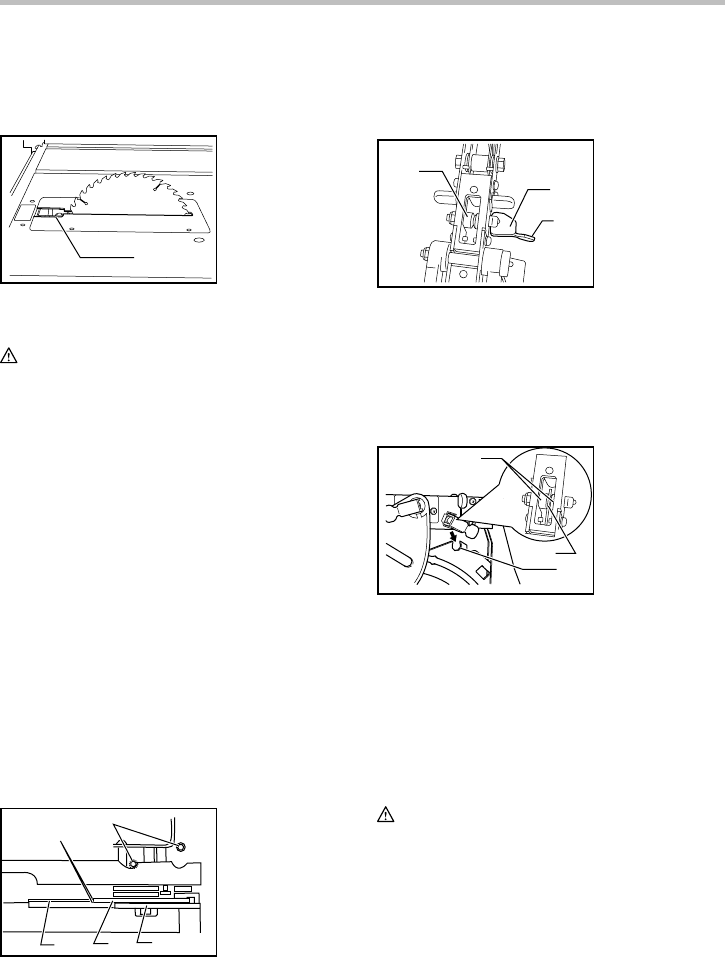
Dado Position
1
Fig.5
008752
Riving Knife/Spreader Alignment
WARNING:
• Always make sure the blade is properly aligned
with the riving knife / spreader. If the blade and
the riving knife / spreader are not aligned this could
cause interference with the feeding and/or the
pinching of the work piece resulting in a kickback
situation and possible serious personal injury.
• NEVER make any adjustments while the tool is
running. Always disconnect the tool before
making any adjustments, accidental start up of the
tool could result in serious personal injury.
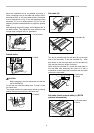
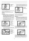
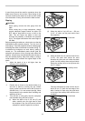
The riving knife / spreader installation is factory-adjusted
so that the blade and the riving knife / spreader are
properly aligned. However, if the blade and the riving
knife / spreader come out of alignment this can be
corrected by first unplugging the tool to prevent
unintentional operation. Then the hex bolts as shown
in item 5 should be loosened using the specially
provided wrench. With the hex bolts loosened adjust
the riving knife/spreader so that it is aligned directly
behind the blade while maintaining equal clearance on
either side of the riving knife / spreader in relation to the
blade as shown in item 1. Once the riving knife
spreader is located properly lock the mounting means
into place by tightening the hex bolts as shown in item 5.
1
2
3
4
5
009009
Blade Guard Assembly Installation or
Removal
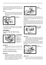
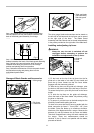
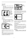
1. Release the locking lever pin of the blade guard
by lifting the locking lever tab as shown in figure 1.
1
2
3
Fig.1
008742
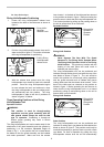
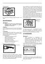
2. For ease of guard assembly installation adjust the
table saw for maximum depth of cut. With the
locking lever released as shown in Figure 1,
position the locking lever pin center groove into
the notch provided on the riving knife/spreader
unit as shown in figure 2.
1
2
3
Fig.2
008743
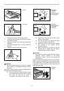
3. Once the locking lever pin is placed into the riving
knife/spreader notch it is to be locked into position
by pushing the tab of the pin's locking lever into
the locked position as shown in Figure 3. Once
the pin's locking lever is in the locked position
check to ensure that the guard assembly is
properly attached to the riving knife/spreader
assembly by pulling up on the guard assembly
and making sure it does not move its position.
WARNING:
• Always ensure proper attachment of the guard
assembly to the Riving Knife/Spreader before
turning the saw on. Improper attachment of the
guard assembly could result in the saw blade
making contact with the guard, causing serious
injury.
1. These two
clearances
should be equal
2. Blade
3. Riving knife/
Spreader
4. Pressure plate
5. Hex bolts
1.
The notch
provided on the
Riving Knife/
Spreader for the
locking lever pin
center groove
2. Locking lever pin
sleeves
3. Locking lever pin
center
g
roove
1. Locking Lever in
the released
position
2. Locking Lever
tab
3. Locking Lever
Pin
1. Riving knife/
Spreader in
Dado Position