


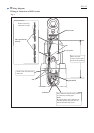
P 11/ 13
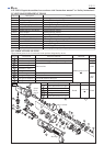
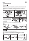
Fig. D-2
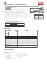
Wiring diagram
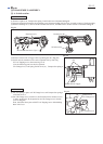
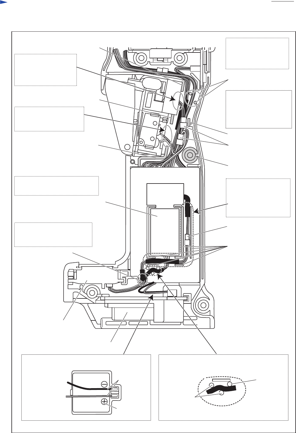
Switch
Terminal
Power supply
circuit
Connector
rib (A)
Wiring around Controller
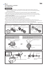
Receptacle
Terminal
Lead wire (black)
Lead wire (red)
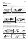
Install Receptacles on Terminal as illustrated below.
Route Lead wires that connects Power supply circuit
with RF unit between three pins as illustrated below.
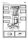
Sponge
Controller
boss
pin
Connector
rib (D)
rib (C)
rib (B)
groove
rib
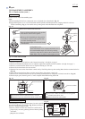
Put Connectors and
the slack portion of
Lead wires in the space
between ribs (A)- (B)- (C)
and pins- rib (D)- boss.
Route Lead wires
(orange, white, blue)
from Controller to Stator
between the two pins.
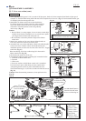
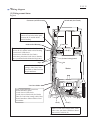
Put Connector and Lead
wires from Controller to
Power supply circuit
between the ribs on
Controller.
Put Lead wires from Controller
to Power supply circuit on the
groove on Controller.
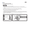
Put Power supply circuit
with Sponge on Housing (L) side.
Route Lead wires from
Switch unit (for Trigger)
between rib (B) and rib (C).
Route Lead wires from
Switch unit (for rotation
reverse) between rib (A)
and rib (C).
RF unit
pin
pin