


P 9/ 13
Repair
[3] DISASSEMBLY/ASSEMBLY
[3] -6. Switch section
DISASSEMBLING
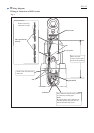
M3x20 Pan head screw (7pcs.)
Housing set (R).
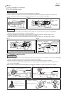
Fig. 31
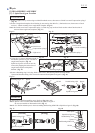
(1) Remove Light cover, Compression spring 2 and Switch lever illustrated in Fig. 12.
(2) Separate Angle head complete from Housing set as illustrated in Fig. 13. However, no need to remove Clutch assembly.
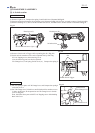
(3) Remove Housing set (L) and seven M3x20 Pan head screws, and then remove Switch section as illustrated in Fig. 31.
Housing set (L)
Switch section
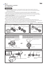
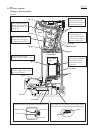
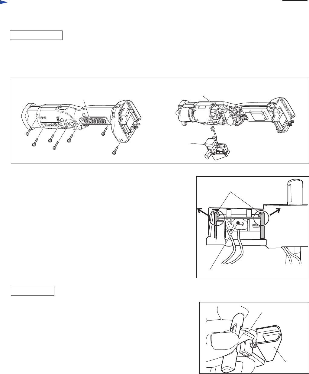
(4) Remove Switch unit in Trigger while expanding the ribs. (Fig. 32)
(5) Switch unit for rotation reverse can be replaced first by removing
PT3x16 T
apping scre
w, then removing Cover.
Now the following parts can also be replaced:
F/R Change lever, Leaf spring, Switch lever (A), Compression spring 4
Fig. 32
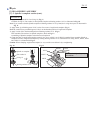
Fig. 33
Switch unit in Trigger
ribs
ASSEMBLING
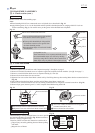
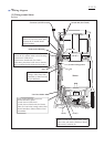
(1) Put Leaf spring in place on F/R Change lever, and Compression spring 4
on Switch lever A.
(2) Put F/R Change lever, Switch lever and Switch unit for rotation reverse
in place; at this time, fit the protrusion on F/R Change lever in Switch
lever A. (Fig. 33)
Then, fasten the above parts with PT3x16 Tapping screw while holding
them with Cover.
protrusion on
F/R Change lever
Switch lever A