


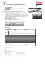
P 6/ 13
Repair
[3] DISASSEMBLY/ASSEMBLY
[3] -4. Clutch section
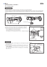
Fig. 22
M5x10 Torx countersunk
head screw
M5x10 Torx countersunk
head screw
783204-6
T25 Torx wrench (T25 of 1R145)
6mm
Spindle
Flat washer 7
Cam A on Torx screw side
Cam D
Cam A on Torx
screw side
Cam A on Torx screw side
Cam D
Spindle
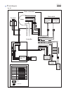
Fig. 21
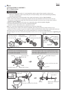
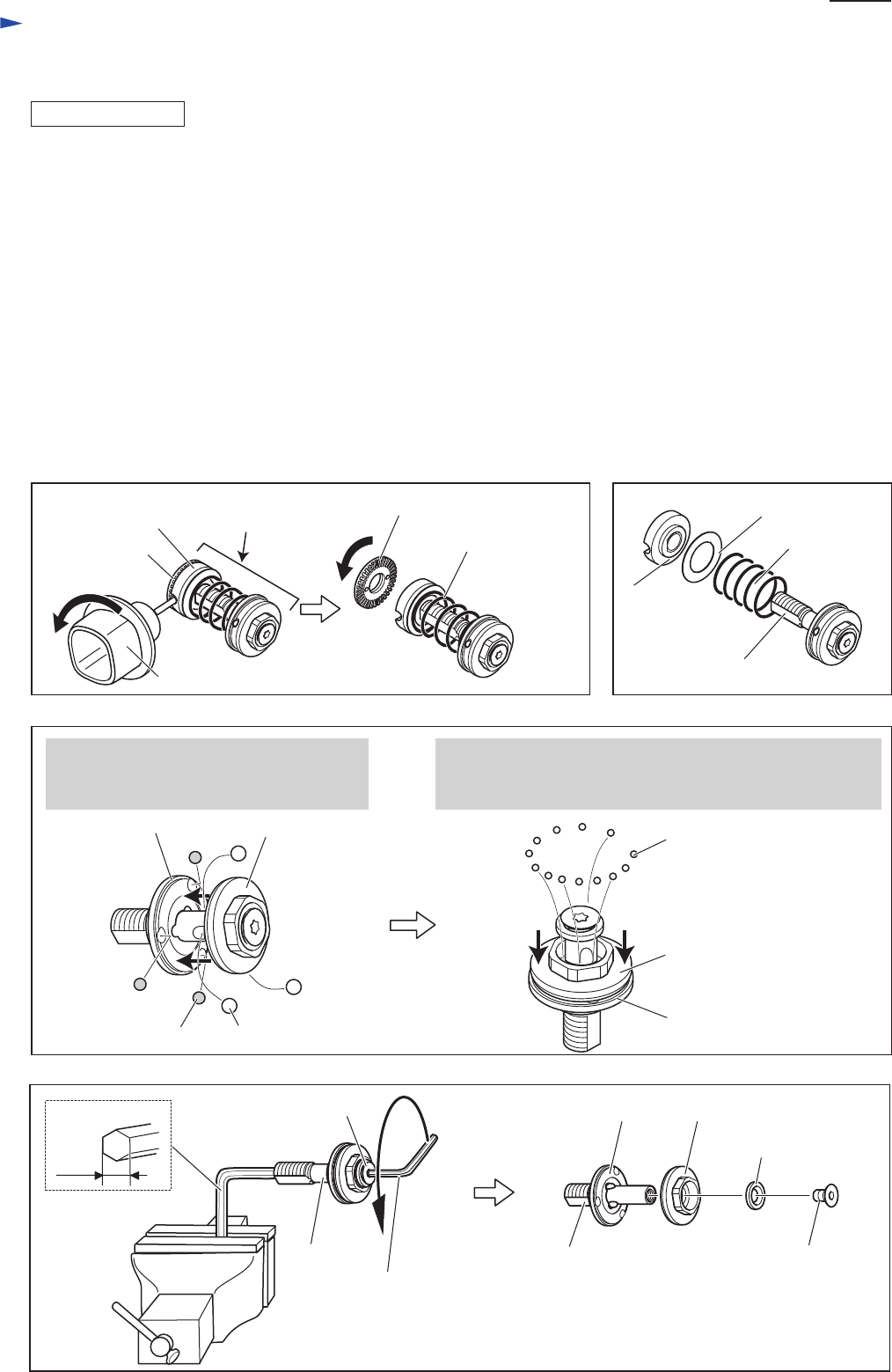
Steel ball 4 (3pcs.) Steel ball 5.0 (3pcs.)
Steel ball 4 (3pcs.) and Steel ball 5.0 (3pcs.)
can be removed by moving Cam D towards
the threaded end of Spindle.
After removing Steel ball 4 (3pcs.) and Steel ball 5.0 (3pcs.),
Steel ball 3 (13pcs.) can be removed by moving *the Cam on
Torx screw side towards Cam D.
Steel ball 3.0 (13pcs.)
Cam D
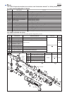
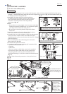
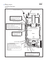
Note: When repairing Clutch section, it is recommended to entirely replace Clutch assembly with new one.
However, if required to replace component parts of Clutch assembly, follow the disassembling/assembling
procedure described below.
1) Take out Clutch section (=Clutch assembly) from Angle head complete. (Refer to Figs. 12 and 13)
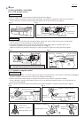
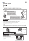
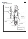
2) Insert 765025-8 into the hole of Adjust ring complete, and turn it counterclockwise to remove M12 Lock nut:
the pressure of Compression spring 19H will be decreased, and M12 Lock nut can now be removed by turning it
clockwise by hand. (Fig. 19)
3) Remove Adjust ring complete, Flat washer 18, Compression spring 19H from Spindle. (Fig. 20)
4) The following Steel balls can be removed as illustrated in Fig. 21:
Steel ball 3 (13pcs.), Steel ball 4 (3pcs.), Steel ball 5.0 (3pcs.)
Note: Use a screwdriver magnetized with 1R288 for easy removal of Steel balls.
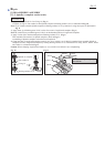
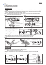
5) Insert short leg of hex wrench 6 into the hole of Spindle, and fix long leg of the hex wrench securely in vise.
Insert No.T25 Torx wrench of L type Torx wrench set (1R145) into the socket of M5x10 Torx countersunk head screw.
Then remove the screw by turning M5 Torx wrench counterclockwise as illustrated to left in Fig. 22.
The following parts can now be removed from Spindle: Cam D, Cam A on Torx screw side, Flat washer 7.(right in Fig. 22)
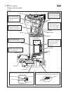
DISASSEMBLING
Flat washer 18
Compression
spring 19H
Compression spring 19H
Adjust ring
complete
Fig. 20
Fig. 19
M12 Lock nut
Adjust ring complete
Clutch section
(=Clutch assembly)
765025-8
M12 Lock nut
Spindle