


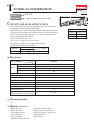
P 8/ 13
Repair
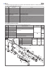
[3] DISASSEMBLY/ASSEMBLY
[3] -5. Gear case section (cont.)
ASSEMBLING
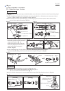
1) After applying Makita grease N No.2 to teeth of all Spur gears, shafts of Carrier complete B and shafts of Spur gear 9
complete A, assemble Ball bearing 6805LLB and Carrier complete B to Gear case. (Fig. 2) Then assemble Internal gear
47 and Spur gears from the opposite side.
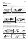
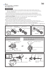
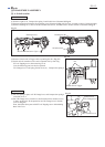
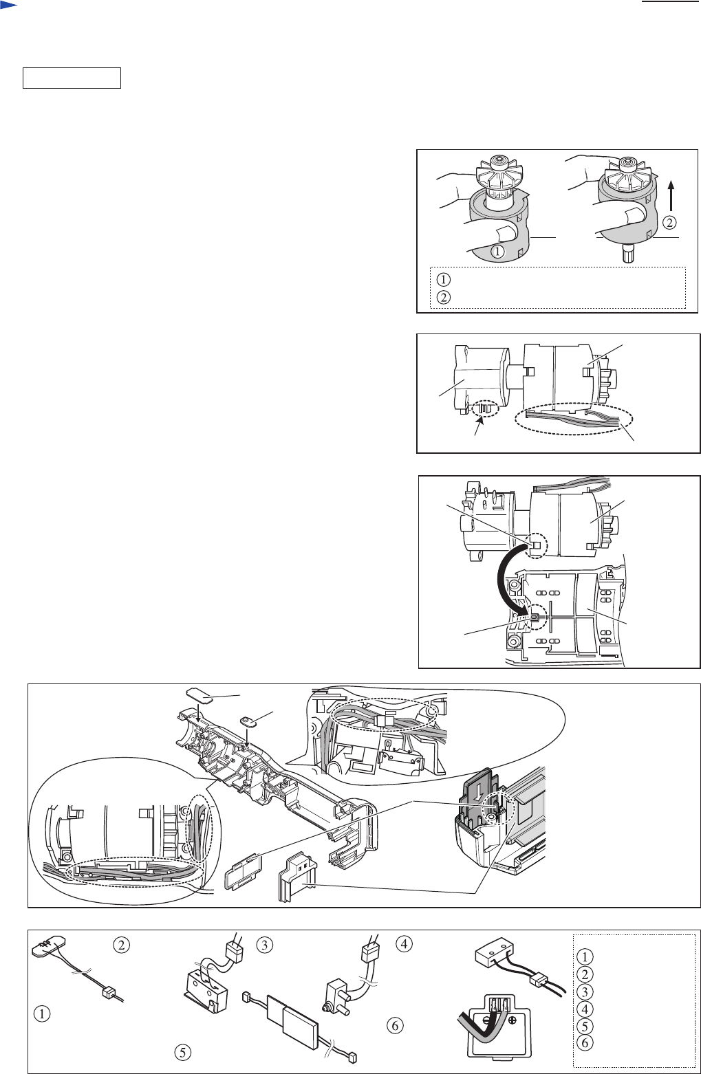
2) Install Rotor on Motor control unit as described below;
Fix Motor control unit on table or the like, and insert Rotor
slowly into Motor control unit until it touches the surface
of the table. Then lift up Motor control unit gradually
until it stops. (Fig. 26)
Caution:
1. Because Rotor is a strong magnet, be sure to remove metal chips
or debris from it before installation, be very careful not to pinch
your fingers between Rotor and metal parts, etc.
2. Be careful not to shock the printed wiring board of Motor
control unit.
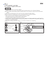
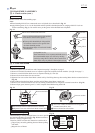
3) Install Lock washer on Gear case, then put Motor bracket on
Gear case, and turn it clockwise to lock in place.
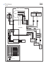
4) Assemble Gear case section and Motor control unit to Housing (R)
so that Lead wires of Motor control unit and the Switch unit
installation portion on Gear case faces the side of the LED - Trigger
switch line. (Fig. 27)
When assembling, fit the boss on Housing (R) in the notch in
Motor control unit. (Fig. 28)
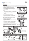
5) Set Switch unit in place on Gear case.
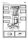
6) Assemble the following parts to Housing (R) in numerical order:
1. Controller of Motor control unit
2. Terminal
3. LED circuit
4. Gear case section to which Motor control unit is assembled
Put Lead wires in place while taking care not to pinch them.
After putting Switch section in place, install Plate and Lens.
Then fasten Housing (L) to (R) with seven M3x20 Pan head screws.
(Fig. 29)
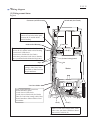
Caution: When disconnecting connectors, do not pull lead wires.
(Fig. 30)
Fig. 26
Fig. 27
Fig. 28
Fix Motor control unit, and insert Rotor.
Lift up Motor control unit until it stops.
Motor
control
unit
Housing (R)
notch
boss
Fig. 29
Fig. 30
Fix lead wires with
lead wire holders.
Fix lead wires with
Lead wire holders.
LED circuit
Switch unit
(ON/OFF)
Switch unit
for Clutch
Power supply circuit
Terminal
Color of Lead wires
Switch unit for
F/R change
Blue, Black
Yellow, White
Yellow, Blue
Purple, Yellow
Red, Black
Positive: Red
Negative: Black
Gear
case
Motor
control
unit
Switch unit installation portion
Lead wires
Cover
Plate
Lens
Terminal
Face the rib of Cover to
Terminal side and insert
the cover to Housing set.
rib of Cover