


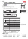
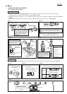
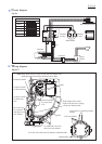
Wiring diagram
P 13 / 13
Fig. D-2
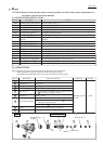
Circuit diagram
Color index of lead wires' sheath
Black
White
Blue
Orange
Yellow
Red
Switch
Terminal
Tape
Light
circuit
LED
Yoke unit
FET
Heat dissipation plate
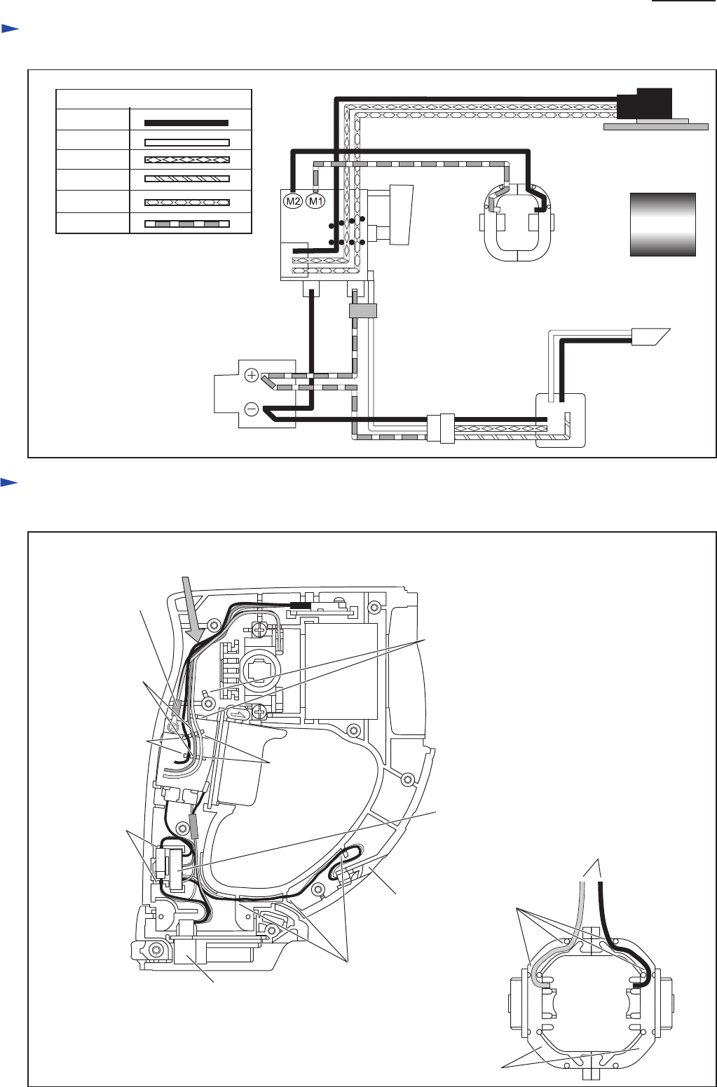
(Housing
L side)
(Housing
R side)
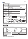
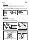
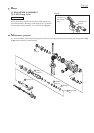
Fig. D-1
Connector
Brush holder
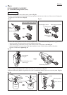
Note: Route Lead wires for switch to each lead wire holders and
guide them between insulated terminal and two Ribs.
Lead wire holder
for black lead
wire
Fix Lead wire
for connector
with these Lead
wire holders.
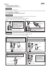
Terminal
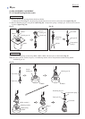
Fix LED lead wires with
these Lead wire holders.
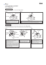
Fix Lead wires with Lead wire holders on Brush holders.
Lead wire holder
for yellow lead
wire
Lead wire holder
for blue lead wire
Insulated terminal
Ribs
LED
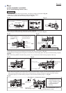
Brush holders
Lead wire holders
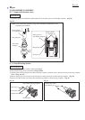
Lead wires for connecting Carbon
brushes
Install Light circuit so that
Light circuit lead wire (orange)
is located to Terminal side.