


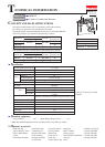
[2] LUBRICATION (cont.)
Repair
P 3 / 13
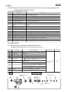
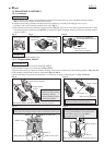
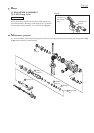
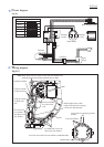
Fig. 2
Item No. Description Portion to lubricate Lubricant Amount
Striker
Ball bearing 606ZZ
Compression spring 7
Disassemble Tool holder section as illustrated in Fig. 3.
Retaining ring S-7
Piston joint
Armature
Flat washer 12
Swash Bearing Section
40
41
51
52 53
63
(f)
(g)
(h) (g)
(k) Crank room
(i)
(j)
50
49
51
52
53
63
17
40
41
Clutch cam
Bearing portion
(k) Crank room
4g
17g
Swash bearing 10
Helical gear 25
Gear housing
complete
Inner housing
complete
O ring 16
Piston cylinder
Whole portion
Makita grease R No. 00
Makita grease R No. 00
Makita grease R No. 00
Molybdenum disulfide
lubricant
Molybdenum disulfide
lubricant
Molybdenum disulfide
lubricant
Makita grease R No. 00
a little
a little
5g
Pole portion which is inserted into Piston joint
49 Spur gear 10 Gear teeth where 28 Spur gear 51 engages (Refer to Fig. 1.)
Teeth portion
Space where Armature's drive end and 53 Helical gear 25
engages
(f) Inside where Striker moves
(g) Hole for accepting Piston joint
(h) Surface where 30 Tool holder complete contacts.
(Refer to Fig. 1.)
(i) Outside groove
(j) Side where 52 Swash bearing 10 engages
50 Cam shaft Surface where 51 Clutch cam and 49 Spur gear 10 contact
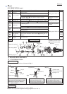
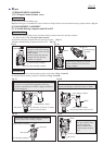
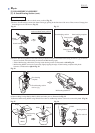
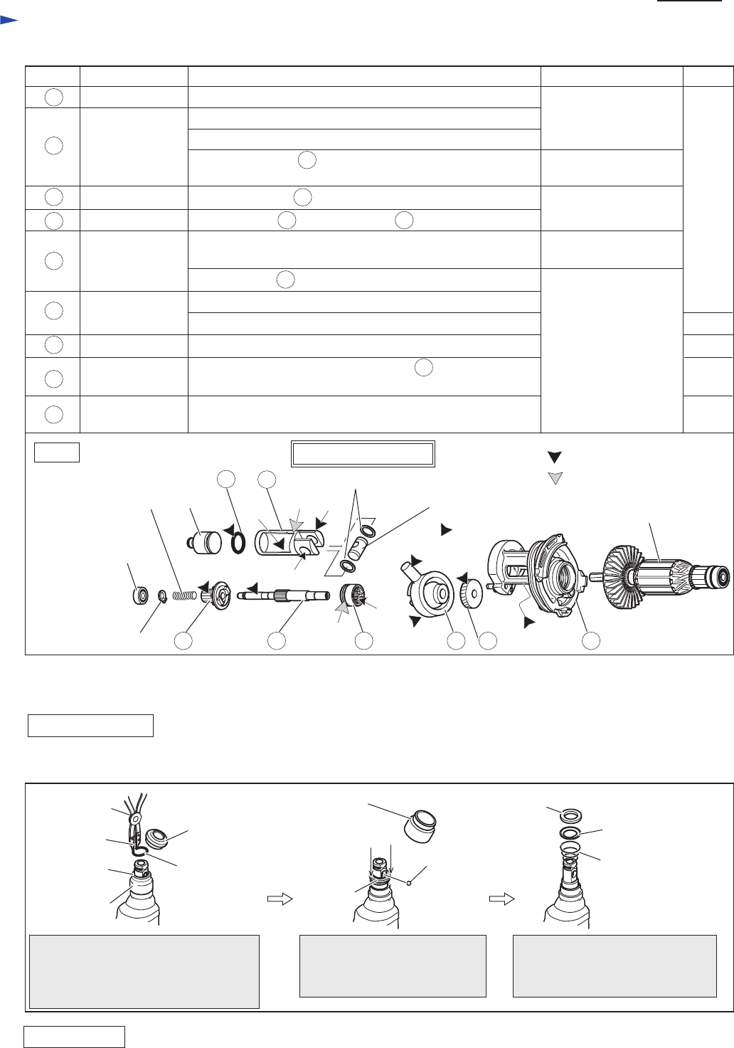
[3] DISASSEMBLY/ASSEMBLY
[3] -1. Tool Holder Section
DISASSEMBLING
Ring 21
Ring 21
Guide washer
Conical compression
spring 21-29
Cap 35
Steel ball 7.0
Chuck cover
Ring
spring 19
Chuck cover
1R003
1R212
Disassemble Cap 35 and remove
Ring spring 19 with 1R003 and 1R212.
Note: Replace the tips of 1R003 to
those of 1R212.
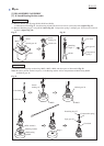
Ring 21
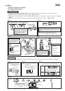
Disassemble Chuck cover.
And remove Steel ball 7.0
while pressing down Ring 21.
After disassembling Steel ball 7.0,
the Tool holder section can be
disassembled as illustrated above.
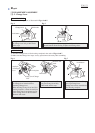
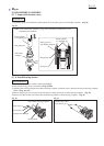
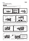
Fig. 3
ASSEMBLING
Do the reverse of the disassembling step. Refer to Fig. 3.
Note: Be sure to place the flat portion of Ring spring 19 on Steel ball 7.0.