


[3] DISASSEMBLY/ASSEMBLY
[3]-4. Motor section, Switch
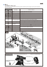
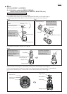
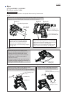
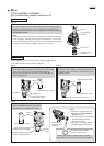
Remove two Pins 6 and two 4x18 Tapping screws,
then separate Handle (R) from Handle (L).
Switch can now be replaced. (Also see Figs. D-1 and D-2.)
Remove two Pins 6 and Handle section from
Housing (L) to disassemble Motor section.
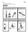
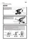
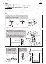
Remove four 4x35 Tapping screws from Gear housing complete and nine 4x18
Tapping screws from Housing (R). Housing (R) can now be removed.
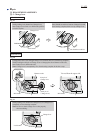
loop portion
of Side grip
DISASSEMBLING
Gear housing complete
Note: Motor section and Switch can be replaced without removing Carbon brushes.
Fig. 22
Fig. 23
4x35 Tapping
screw (4pcs.)
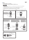
Note:
For easier repair, except when repairing
Motor section, it is recommended not to
remove two 4x35 Tapping screws that
fasten Housing (L) to Gear housing complete.
(See Fig. 23.)
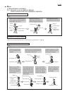
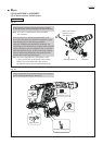
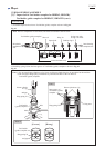
Note:
Except when replacing Switch, it is recommended
not to remove two 4x18 Tapping screws that fasten
Handle (R) to Handle (L). (See Fig. 24.)
With the screws left untightened, Handle section
can be removed as an assembly. (See Fig. 25.)
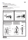
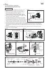
When removing four 4x35 Tapping screws
from Gear housing complete and nine 4x18
Tapping screws from Housing (R), put the
loop portion of Side grip between workbench
and Housing (L) as drawn on the right for
efficient disassembly.
Without the support of Side grip, Gear housing
complete will tend to separate from Housing (L),
causing the machine to fall apart.
Fig. 24 Fig. 25
Housing (L)
Housing (R)Handle (R)
Pin 6
(2pcs.)
Pin 6
(2 pcs.)
Handle (R)
Handle (L)
4x18 Tapping screw
(2 pcs.)
Compression
spring 10 (2 pcs.)
Handle section
[assembly of Handles (R) and (L)]
4x18 Tapping screw
(9pcs.) on Housing (R)
4x18 Tapping screw
(2pcs.) on Handle (R)
Repair
P 10/22