


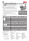
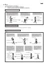
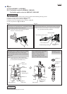

Gear section: 17g
Crank section: 5g
boss for fixing
Compression
spring 14
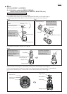
[Inside view of Inner housing]
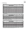
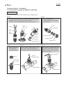
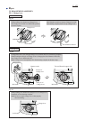
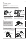
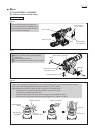
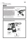
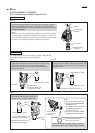
[2] LUBRICATION (cont.)
Apply Makita grease RB No.00 to the following portions indicated by black triangle to protect parts and product
from unusual abrasion.
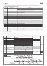
Fig. 2
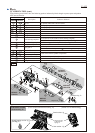
Fig. 3
BHR262
HR262D
BHR262T
HR262T
Item No.
Description Portion to lubricate
[Cross section around Swash bearing 10]
Cap 35
O ring 17
1
16
Change lever13
Gear housing complete
Spur gear 51
17
28
Steel ball 7
(a)
(b)
29
Tool holder complete
Tool holder guide complete
30
Lip portion where Bit is to be inserted
Entire surface
Pins
(b) Inside where Swash bearing section rotates (See Fig. 3.)
(c) Gear portion
(a) Oil seal 25 on the inside of Gear housing complete
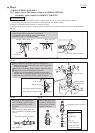
Entire surface
Inside where Piston cylinder reciprocates
Impact bolt
Impact bolt
Cushion ring 13
16
13
28
Lock plate complete23 Pins
Needle bearing complete19 Needle bearing portion in Cup washer (See Fig. 37.)
17
111
114
115
30
Ring 21
Stopper
4
Inner periphery
Inner periphery
Sleeve 932 Inside where Impact bolt reciprocates
Ring 1034 Portion that contacts Cushion ring 13
Entire surface
O ring 937
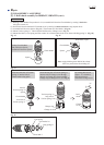
(d) Surface where Clutch portion of 30 Tool holder (guide) complete contacts
(d)
BHR262T
HR262TD
(c)
120 Steel Ball 6 (2 pcs.) Entire surface
124 Steel Ball 5 Entire surface
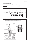
Repair
P 4/22
BHR262
HR262D
19
23
BHR262
HR262D
32
34
37
114
124
120
111
4
1
30
30
29
115
BHR262T
HR262TD
Lubrication Around
Swash bearing 10
Swash bearing section: 4g
(See Fig. 1.)