


[2] LUBRICATION
[1] NECESSARY REPAIRING TOOLS
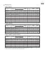
Repair
DescriptionCode No. Use for
Retaining ring S pliers ST-2N1R003
Removing Ring spring 19 from Tool holder complete/ Tool holder guide complete
Retaining ring S pliers ST-2
Bearing plate (for arbor press)
1R004 Removing Ring spring 29
1R022 or
1R356
Removing Ring spring 29
Bearing setting plate 8.21R032 Assembling Spiral bevel gear 26
Assembling Spiral bevel gear 26Bearing setting plate 10.21R033
Ring spring setting tool A1R164 Assembling Oil seal 25 to Gear housing complete
Ring spring setting tool B1R165 Assembling Needle bearing complete to Gear housing complete
Tip for Retaining ring pliers1R212 Attachment of 1R003
T-type hex wrench 3-1271R170 Removing two M4x25 hex socket head bolts on Inner support complete
Drill chuck extractor1R139 Removing Spiral bevel gear 26
Pipe 301R232 Assembling Oil seal 25 to Gear housing complete
Round bar for arbor 24-1001R249 Removing Ring spring 28
Round bar for arbor 30-1001R252 Removing Oil seal 25 from Gear housing complete
Bearing extractor1R269 Removing Ball bearing 608ZZ from Inner support complete
Round bar for arbor 7-501R281 Removing Ring 8
1R291 Removing Retaining Ring S-7
Ring spring removing jig1R306 Removing Ring spring 29 from Tool holder complete/ Tool holder guide complete
Piston cylinder318132-2 Assembling Ring spring 28 to Tool holder complete/ Tool holder guide complete
Retaining ring S and R pliers
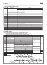
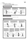
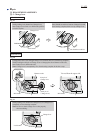
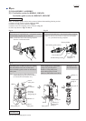
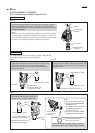
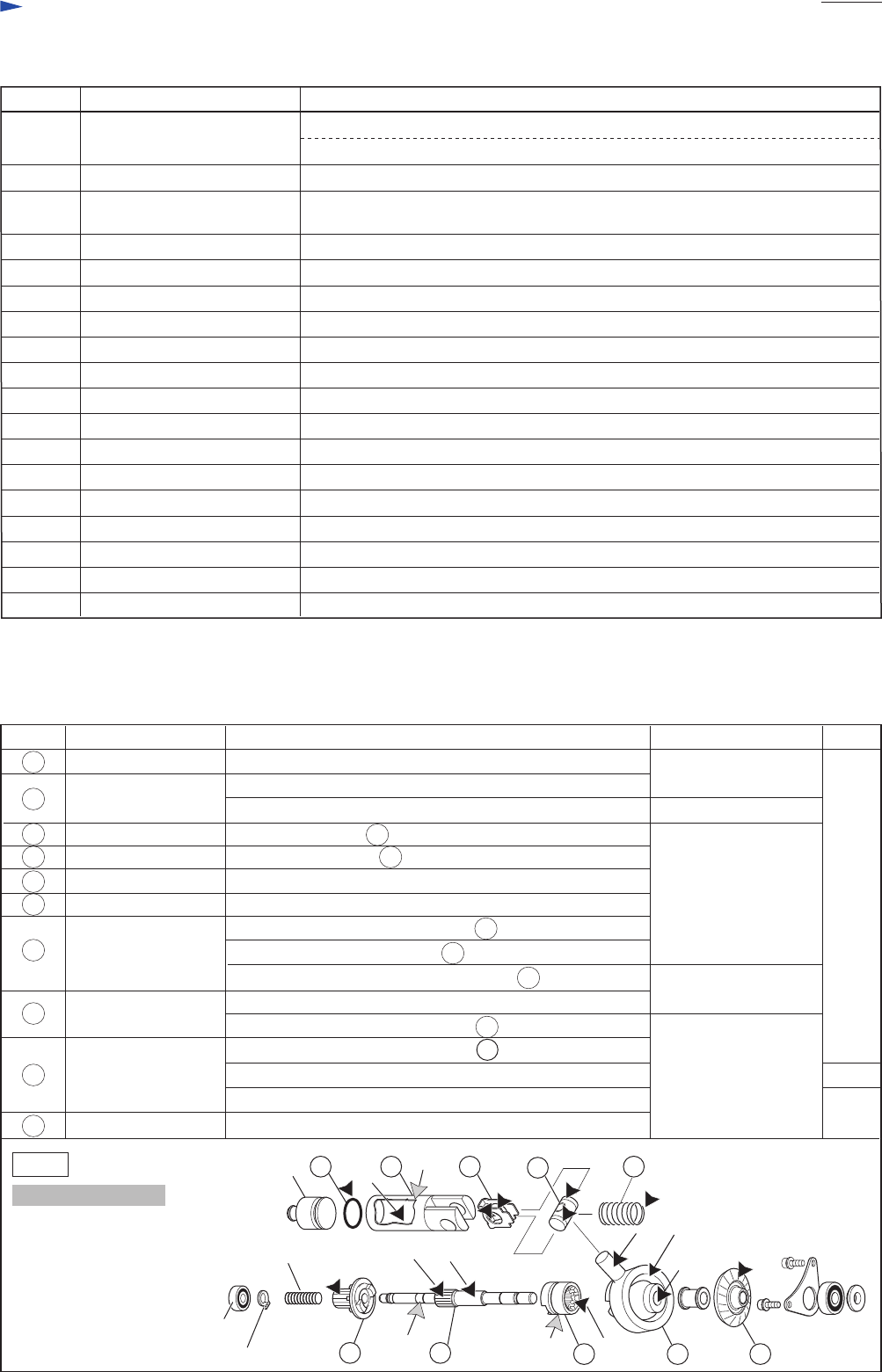
Apply the following grease to protect parts and product from unusual abrasion.
* Makita grease RB No.00 to the portions indicated by black triangle
* Molybdenum disulfide lubricant to the portions indicated by gray triangle
P 3/22
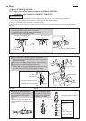
CAUTION: Repair the machine in accordance with “Instruction manual” or “Safety instructions”.
Removing Retaining ring WR-12 from Armature shaft
Fig. 1
Item No. Description Portion to lubricate Lubricant
Makita grease RB No.00
Makita grease RB No.00
Makita grease RB No.00
4g
Amount
a little
a little
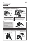
Striker
Compression spring 14 End to be fixed to the boss in Inner housing complete
Ball bearing
606ZZ
Compression spring 7
Retaining ring S-7
(f)
(h)
(i)
(j)
42
44
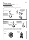
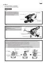
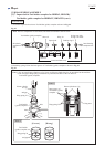
Piston joint Grooves that contact 42 Guide plate
43
50
51
40
41
Clutch cam
Swash bearing 10
O ring 16
Piston cylinder
Guide plate Inside that contacts 43 Piston joint
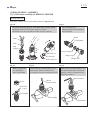
48
Spur gear 10 Gear portion that engages with Spur gear 51
Whole surface
(h) Pole portion to be inserted into 43 Piston joint
(j) Inside of hole
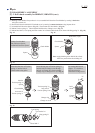
53
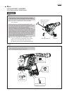
Spiral bevel gear 26 Gear portion that engages with Armature shaft gear
(a) Inside where Striker moves
(b) Outside that contacts Tool holder (guide) complete
49 Cam shaft
(e) Small diameter portion to be inserted into 48 Spur gear 10
(f) Groove for hooking Change plate
(i) Ball bearing portion (See Fig. 3.)
(c) Gear portion that engages with 50 Clutch cam
(d) Portion to be inserted into 51 Swash bearing 10
(g) Gear portion that engages with 49 Cam shaft
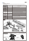
40 41
50
48
51 53
49
42 43 44
(a)
(c) (d)
(b)
(g)
Molybdenum disulfide
Molybdenum disulfide
(e)
Transmission parts