


[3] DISASSEMBLY/ASSEMBLY
[3]-8. Swash bearing 10, Gear section (cont.)
ASSEMBLING
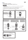
Fig. 51
Fig. 52
Guide plate
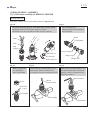
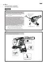
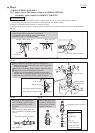
Note: Be sure to apply Makita grease RB No.00 and Molybdenum disulfide
lubricant to the specific portions shown in Figs. 1, 2 and 3.
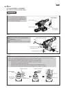
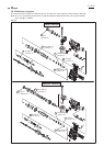
1) Onto Cam shaft, slide Swash bearing 10, Sleeve 9, Spiral bevel gear 26
in order, then press-fit them using 1R032, 1R033 and arbor press.
2) Slide Bearing retainer B onto Cam shaft in advance, then press-fit
Ball bearing 608ZZ then Ring 8 onto the shaft; be careful not to fix
Bearing retainer B between the bearing and Spiral bevel gear26.
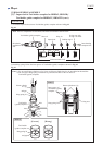
3) Onto Cam shaft, slide Super gear 10 and Compression spring 7 in order,
then secure them with Retaining ring S-7 using 1R291.
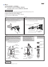
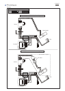
4) Mount Guide plate then Piston joint to Piston cylinder. (Fig. 51)
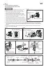
5) Fit Compression spring 14 over the boss of Inner housing complete.
(Figs. 3 and 52)
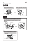
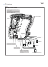
6) Insert the pole of Swash bearing 10 through the hole of Piston joint,
then mount Swash bearing portion into Inner housing complete.
Secure Swash bearing portion by fixing Bearing retainer B to Inner
housing complete with two M4x12 Hex socket head bolts. (Fig. 53)
Note: Be sure to apply adhesive to the threads of the two M4x12
Hex socket head bolts.
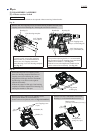
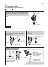
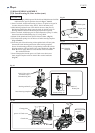
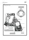
7) Insert Change plate into the groove of Clutch cam, then secure
Inner support complete with two M4x25 Hex socket head bolts.
(Fig. 54)
Fig. 53
Fig. 54
Piston joint
Piston cylinder
1
2
Bearing retainer B
Inner housing complete
groove of Clutch cam
Change plate
M4x12 Hex socket
head bolts (2pcs.)
Threadlocking bolt
Inner support
complete
Compression spring 14
pole of
Swash bearing 10
hole of
Piston joint
Inner housing
complete
Clutch cam
Repair
P 18/22
Swash bearing portion