


Note: 2)
ASSEMBLING
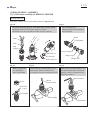
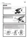
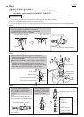
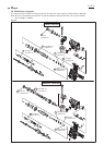
Fig. 42
Cushion ring 13
Ring 10
O ring case with
O ring 9 fit inside
Impact bolt
1) Assemble Impact bolt section to Tool holder (guide) complete as drawn in Fig. 42.
Tool holder (guide) complete
Sleeve 9
Bit (chuck)
installation
side
Inner housing
complete side
long short
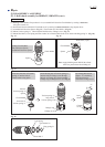
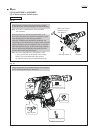
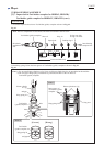
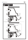
Fig. 43
Note: 1) Use an extra Piston cylinder as a jig. Never use Piston cylinder that is to be assembled to the machine.
2) The end gap of Ring spring 28 must not be positioned in either of the two holes of
Tool holder (guide) complete.
2) Push Ring spring 28 into the inner groove of Tool holder (guide) complete as drawn in Fig. 43.
Piston cylinder
as a jig
Piston cylinder as a jig
Tool holder
(guide) complete
end gap
hole
Inner groove of
Tool holder (guide)
complete
Ring spring 28
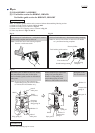
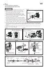
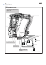
O ring case
Note: The five components are directional, and must be mounted as shown below.
hole
[3] DISASSEMBLY/ASSEMBLY
[3]-7. Impact bolt in Tool holder complete for BHR262, HR262D)/
Tool holder guide complete for BHR262T, HR262TD (cont.)
Repair
P 16/22
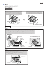
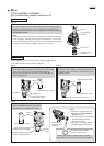
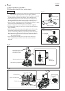
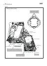
[cross-sectional view]
Ring spring 28
Tool holder
(guide) complete
end gap
Ring spring 28
[Correct] [Wrong]
Note: 1)