


41
CRADLE AND CABLE TERMINATIONS
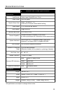
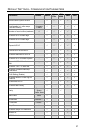
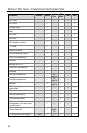
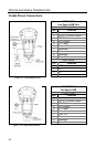
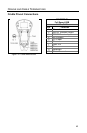
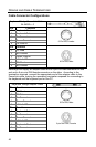
Cradle Pinout Connections
There are interface and power ports located on the bottom of each MI9535-5
xx
cradle. The number of ports and type of connection varies by cradle model and
the interface required. The following charts provide the pinout information for the
different cradle models and interfaces available.
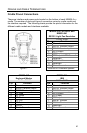
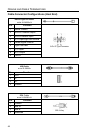
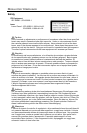
MI9535-514 Full RS232 and
MI9535-541
RS232 / Light Pen Emulation
10-Pin, RJ45
Pin Function
1 Ground
2 RS232 Transmit Output
3 RS232 Receive Input
4 RTS Output
5 CTS Input
6 DTR Input / LTPN Source*
7 Reserved
8 LTPN Data*
9 Reserved
10 Shield Ground
Figure 17.
* MI9535-541 Interface Specific
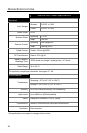
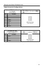
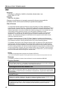
MI9535-547
Keyboard Wedge
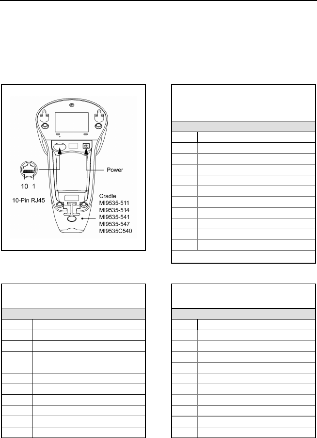
MI9535-511
IBM
10-Pin, RJ45 10-Pin, RJ45
Pin Function Pin Function
1 Ground 1 Ground
2 RS232 Transmit Output 2 RS232 Transmit Output
3 RS232 Receive Input 3 RS232 Receive Input
4 PC Data 4 RTS Output
5 PC Clock 5 CTS Input
6 KB Clock 6 DTR Input
7 PC +5V 7 IBM B- Transmit
8 KB Data 8 IBM A+ Receive
9 +5VDC 9 Reserved
10 Shield Ground
10 Shield Ground