


OM-203 034 Page 18
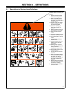
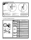
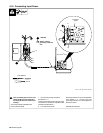
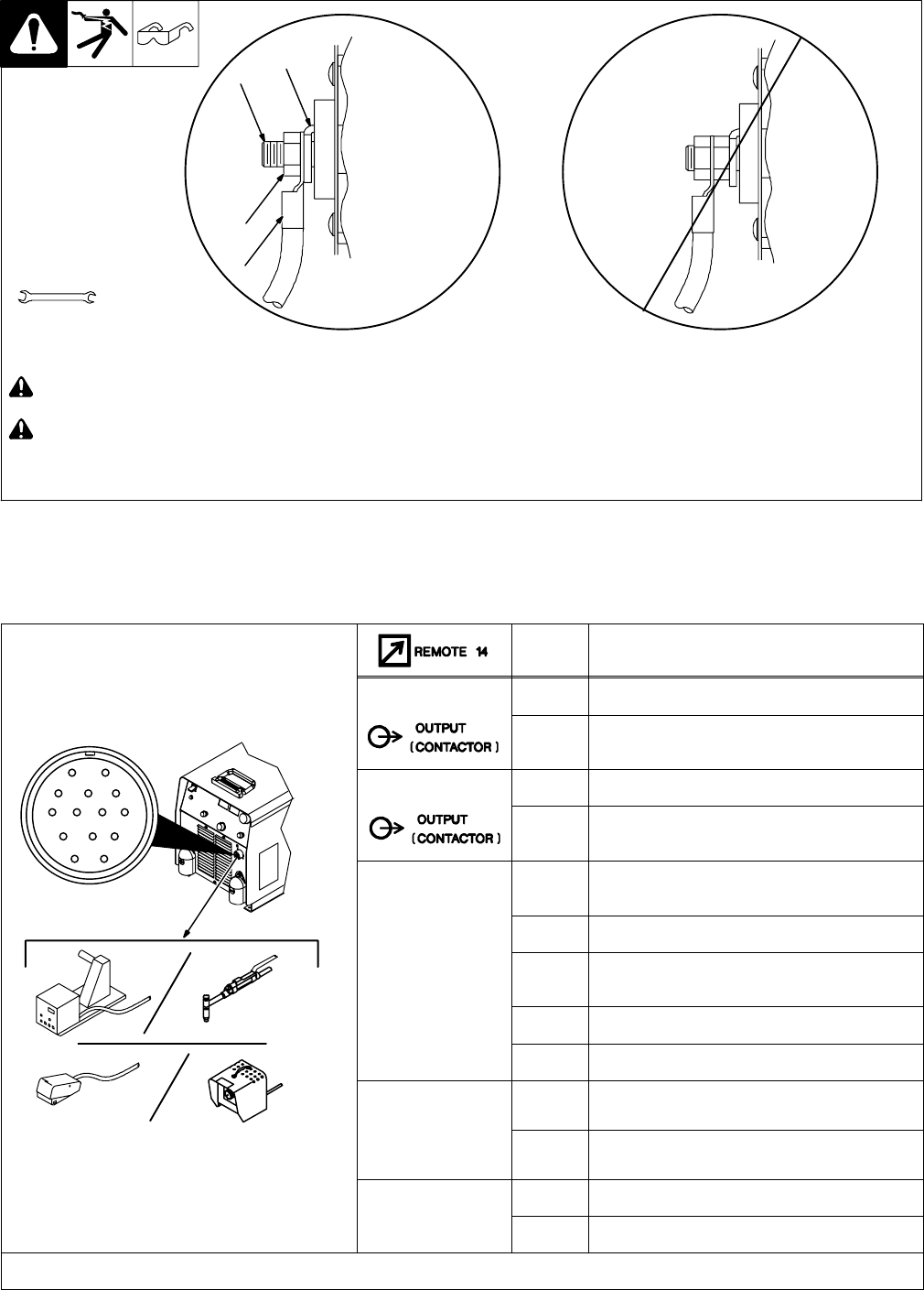
4-8. Connecting Weld Output Cables
803 778-B
! Turn off power before connecting to
weld output terminals.
! Failure to properly connect weld
cables may cause excessive heat
and start a fire, or damage your ma-
chine.
1 Weld Output Terminal
2 Supplied Weld Output Terminal Nut
3 Weld Cable Terminal
4 Copper Bar
Remove supplied nut from weld output ter-
minal. Slide weld cable terminal onto weld
output terminal and secure with nut so that
weld cable terminal is tight against copper
bar. Do not place anything between weld
cable terminal and copper bar. Make
sure that the surfaces of the weld cable
terminal and copper bar are clean.
Tools Needed:
3/4 in (19 mm)
4
2
3
Do not place
anything between
Incorrect Installation
1
weld cable terminal
and copper bar.
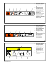
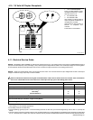
4-9. Remote 14 Receptacle Information
Ref. 802 260
AJ
B
K
I
C
L
NH
D
M
G
E
F
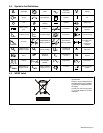
Socket* Socket Information
24 VOLTS AC
A 24 volts ac. Protected by circuit breaker CB2.
B Contact closure to A completes 24 volts ac con-
tactor control circuit.
115 VOLTS AC
I 115 volts ac. Protected by circuit breaker CB1.
J Contact closure to I completes 115 volts ac con-
tactor control circuit.
REMOTE
OUTPUT
CONTROL
C Output to remote control; +10 volts dc in MIG
mode.
D Remote control circuit common.
E 0 to +10 volts dc input command signal from re-
mote control.
M Mode select.
N Remote inductance control.
A/V
AMPERAGE
VOLTAGE
F Current feedback; +1 volt dc per 100 amperes.
H Voltage feedback; +1 volt dc per 10 arc volts.
GND
G Circuit common for 24 and 115 volts ac circuits.
K Chassis common.
*The remaining sockets are not used.