


OM-203 034 Page 28
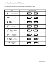
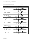
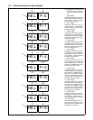
6-4. Voltmeter/Ammeter Help Displays
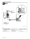
. All directions are in reference to
the front of the unit. All circuitry
referred to is located inside the
unit.
1 Help 0 Display
Indicates a shorted thermistor RT2
on the left side of the unit. If this dis-
play is shown, contact a Factory
Authorized Service Agent.
2 Help 1 Display
Indicates a malfunction in the pri-
mary power circuit. If this display is
shown, contact a Factory Autho-
rized Service Agent.
3 Help 2 Display
Indicates a malfunction in the ther-
mal protection circuitry located on
the left side of the unit. If this display
is shown, contact a Factory Autho-
rized Service Agent.
4 Help 3 Display
Indicates the left side of the unit has
overheated. The unit has shut down
to allow the fan to cool it (see Sec-
tion 4-2). Operation will continue
when the unit has cooled.
5 Help 4 Display
Indicates a malfunction in the ther-
mal protection circuitry located on
the right side of the unit. If this dis-
play is shown, contact a Factory
Authorized Service Agent.
6 Help 5 Display
Indicates the right side of the unit
has overheated. The unit has shut
down to allow the fan to cool it (see
Section 4-2). Operation will contin-
ue when the unit has cooled.
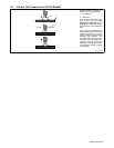
7 Help 6 Display
Indicates that the input voltage is
too low and the unit has automati-
cally shut down. Operation will con-
tinue when the voltage is within
±15% of the operating range. If this
display is shown, have an electri-
cian check the input voltage.
8 Help 7 Display
Indicates that the input voltage is
too high and the unit has automati-
cally shut down. Operation will con-
tinue when the voltage is within
±15% of the operating range. If this
display is shown, have an electri-
cian check the input voltage.
9 Help 8 Display
Indicates a malfunction in the sec-
ondary power circuit of the unit. If
this display is shown, contact a
Factory Authorized Service Agent.
10 Help 9 Display
Indicates a shorted thermistor RT1
on the right side of the unit. If this
display is shown, contact a Factory
Authorized Service Agent.
2
AV
3
AV
4
AV
HE.L P−1
HE.L P−2
HE.L P−3
5
AV
HE.L P−4
6
AV
HE.L P−5
7
AV
HE.L P−6
8
AV
HE.L P−7
9
AV
HE.L P−8
AV
HE.L P−0
AV
HE.L P−9
10
1