


OM-203 034 Page 20
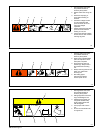
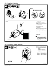
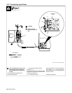
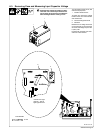
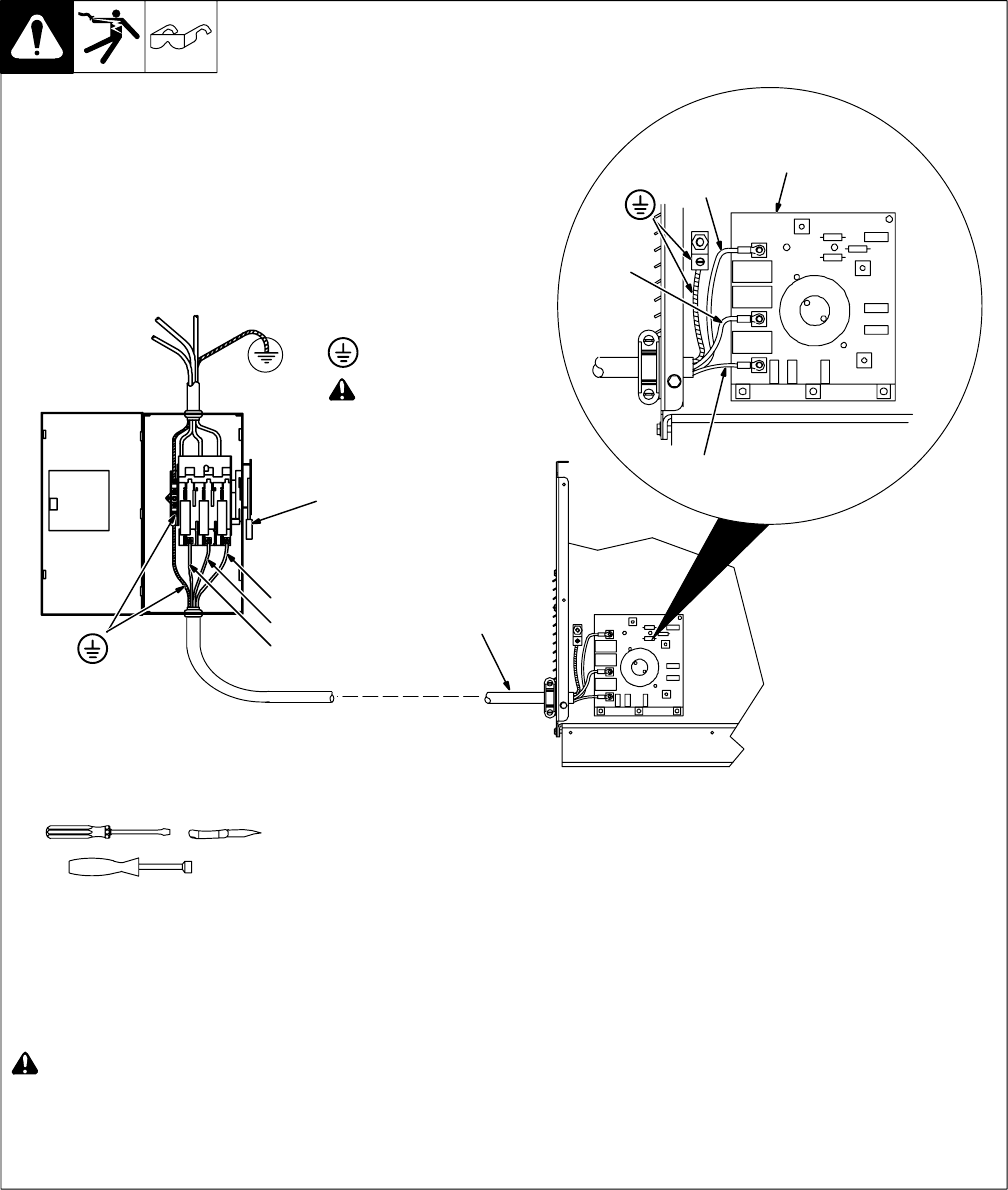
4-12. Connecting Input Power
ssb2.4* 1/94 − 801 523-B / 801 946
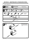
Tools Needed:
5/16 in
Input Filter
Board
L1
=GND/PE
! Turn Off welding power source, and
check voltage on input capacitors
according to Section 6-3 before pro-
ceeding.
Check input voltage available at site.
Remove left side panel.
1 Input And Grounding Conductors
See Section 4-11.
Install ring terminals of proper size onto input
conductors for connection to input filter board
terminals (see illustration).
2 Line Disconnect Device
Select type and size of overcurrent protection
using Section 4-11. Connect input and
grounding conductors to a deenergized line
disconnect device.
Reinstall left side panel.
L1
2
L2
L3
1
L2
L3
! Always connect
grounding conductor
first.