


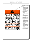
OM-203 034 Page 19
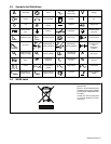
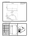
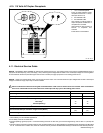
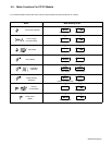
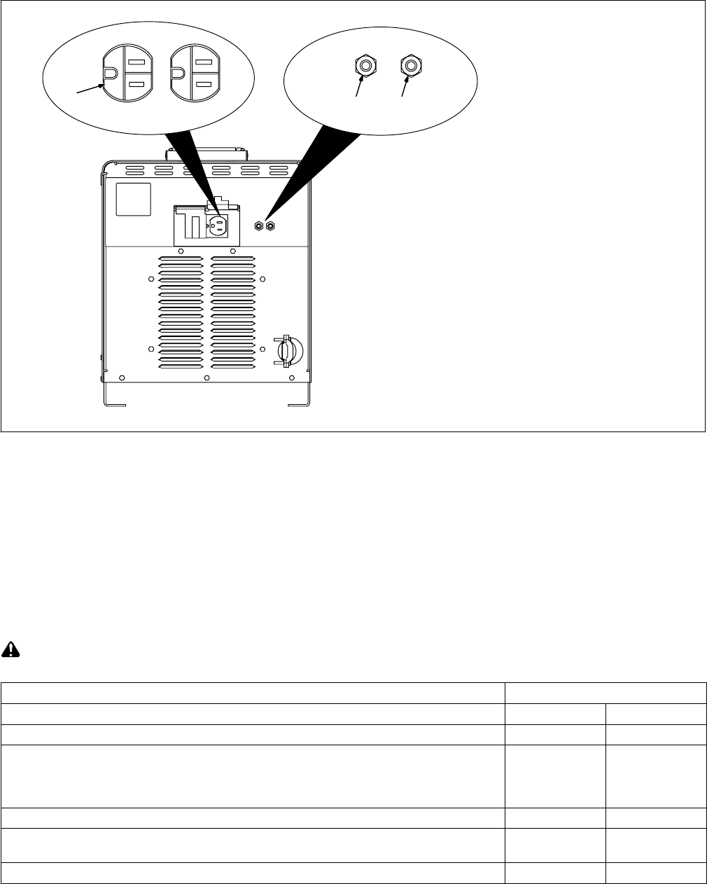
4-10. 115 Volts AC Duplex Receptacle
Ref. 801 524-A
1 115 V 7 A AC Receptacle
Power is shared between duplex
receptacle and Remote 14 recep-
tacle (see Section 4-9).
2 Circuit Breaker CB1
3 Circuit Breaker CB2
CB1 protects 115 volts ac portion of
duplex receptacle and Remote 14
receptacle from overload.
CB2 protects 24 volts ac portion of
Remote 14 receptacle from
overload.
Press button to reset breaker.
2 3
1
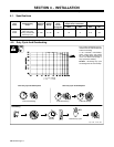
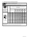
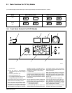
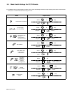
4-11. Electrical Service Guide
NOTICE − INCORRECT INPUT POWER can damage this welding power source. This welding power source requires a CONTINUOUS supply of
input power at rated frequency(+10%) and voltage (+10%). Phase to ground voltage shall not exceed +10% of rated input voltage. Do not use a genera-
tor with automatic idle device (that idles engine when no load is sensed) to supply input power to this welding power source.
NOTICE − Actual input voltage should not be 10% less than minimum and/or 10% more than maximum input voltages listed in table. If actual input
voltage is outside this range, output may not be be available.
Failure to follow these electrical service guide recommendations could create an electric shock or fire hazard. These recommenda-
tions are for a dedicated branch circuit sized for the rated output and duty cycle of the welding power source.
50 Hz Three Phase
Input Voltage 380 400
Input Amperes At Rated Output 33 31
Max Recommended Standard Fuse Rating In Amperes
1
Time-Delay
2
40 35
Normal Operating
3
50 45
Min Input Conductor Size In AWG
4
10 10
Max Recommended Input Conductor Length In Feet (Meters)
181
(55)
201
(61)
Min Grounding Conductor Size In AWG
4
10 10
Reference: 2005 National Electrical Code (NEC) (including article 630)
1 Consult factory for circuit breaker applications.
2 “Time-Delay” fuses are UL class “RK5” .
3 “Normal Operating” (general purpose - no intentional delay) fuses are UL class “K5” (up to and including 60 amp), and UL class “H” ( 65 amp and
above).
4 Conductor data in this section specifies conductor size (excluding flexible cord or cable) between the panelboard and the equipment per NEC Table
310.16. If a flexible cord or cable is used, minimum conductor size may increase. See NEC Table 400.5(A) for flexible cord and cable requirements.