


. A complete Parts List is available at www.MillerWelds.com
OM-4419 Page 25
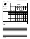
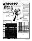
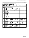
ELECTRODE
DC*
AC
POSITION
PENETRATION
USAGE
MIN. PREP, ROUGH
HIGH SPATTER
GENERAL
SMOOTH, EASY,
FAST
LOW HYDROGEN,
STRONG
SMOOTH, EASY,
FASTER
CAST IRON
STAINLESS
DEEP
DEEP
LOW
MED
LOW
LOW
LOW
LOW
ALL
ALL
ALL
ALL
ALL
FLAT
HORIZ
FILLET
ALL
ALL
EP
EP
EP,EN
EP,EN
EP
EP,EN
EP
EP
6010
6011
6013
7014
7018
7024
NI-CL
308L
*EP = ELECTRODE POSITIVE (REVERSE POLARITY)
EN = ELECTRODE NEGATIVE (STRAIGHT POLARITY)
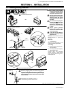
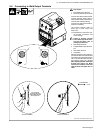
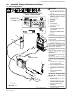
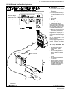
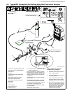
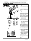
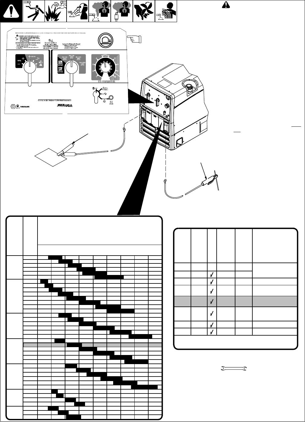
6-3. Typical Stick Welding Connections And Control Settings
803 750-B / 228 201-B / 087 985-A / Ref. S-0653
! Stop engine.
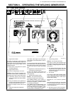
. This section provides general
guidelines and may not suit all
applications.
. The control panel shows the typi-
cal settings for welding with a
7018 (1/8 in) electrode. Consult
the amperage selection tables
below if welding with other elec-
trodes.
1 Work Clamp
2 Electrode Holder
Connect Work cable to Work terminal
and Electrode holder cable to Elec-
trode terminal on welding generator.
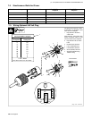
. Be sure to use the correct size
weld cables (see Section 5-7).
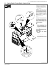
. For best performance, set the
Coarse Range switch to the low-
est range that covers the desired
weld amperage. Use the Fine
control to select the desired am-
perage within the range se-
lected. When properly set, the
Fine control is normally set at 7
or higher.
Typical Settings For 7018 (1/8 in)
Electrode:
> Set Weld Process Selector
switch to + Stick position.
> Set Coarse Range switch to
60-140 (1/8”) position.
> Set Fine control at 7 or higher
for best results.
1
2
3/32
1/8
5/32
3/16
7/32
1/4
1/16
5/64
3/32
1/8
5/32
3/16
7/32
1/4
3/32
1/8
5/32
3/16
7/32
1/4
3/32
1/8
5/32
3/16
7/32
1/4
3/32
1/8
5/32
3/16
7/32
1/4
3/32
1/8
5/32
3/16
3/32
1/8
5/32
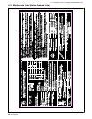
6010
&
6011
6013
7014
7018
7024
Ni-Cl
308L
50
100
150
200
250
300
350
400
450
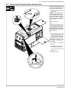
ELECTRODE
AMPERAGE
RANGE
DIAMETER
Electrode Selection Table (Beneath Cover)
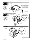
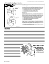
Tools Needed:
For best arc starts and best
results using weld and generator
power together, use a low
Coarse Range setting and the
Fine control set at 7 or higher.
3/4 in
Typical Settings For 7018 (1/8 in) Electrode