


. A complete Parts List is available at www.MillerWelds.com
OM-4419 Page 28
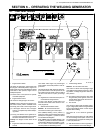
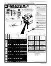
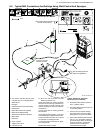
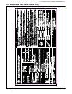
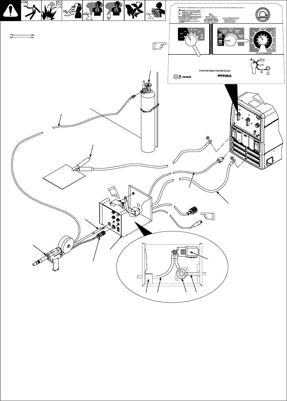
6-5. Typical MIG Connections And Settings Using Weld Control And Spoolgun
802 750-B / 228 201-B
. This section provides general guide-
lines and may not suit all applications.
1 Weld Control
2 Spoolgun
3 Optional Contactor (Recommended)
4 Reed Switch
5 Weld Cable (Customer-Supplied)
6 Weld Control Weld Terminal
7 Weld Power Cable From Spoolgun
8 Work Clamp
9 Gas Hose
10 Argon Cylinder
11 Trigger Control Cord
12 Input Power Cord
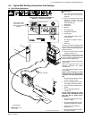
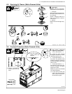
. Be sure to use the correct size weld
cables (see Section 5-7).
Route weld cable from welding generator
Electrode terminal through reed switch to
unused contactor terminal. Connect weld
cable from spoolgun to weld control weld ter-
minal (item 6).
Connect work cable to welding generator
Work terminal.
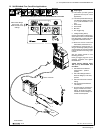
Insert trigger control plug (item 11) into weld
control receptacle. Tighten threaded collar.
Connect ac power cord (item 12) to 120 volt
ac receptacle on welding generator.
Connect gas hose from spoolgun to regula-
tor on Argon bottle.
Reinstall weld control wrapper.
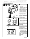
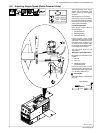
Typical Settings For 4043 (.035)
Aluminum On 1/8 in Material:
> Set Weld Process Selector switch to
Wire + (DCEP) position.
> Set Coarse Range switch to Wire/Low
(17-22 volts) position.
> Set Fine Control to desired voltage
(arc length). Start with a low voltage
setting (about 4) to prevent burnback.
> Set wire feed speed between 240-270
ipm. For 1/4 in. and thicker materials,
set Coarse Range switch to Wire/High
and Fine Control to 6. Increase/de-
crease Fine Control setting to in-
crease/decrease arc length.
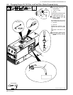
Plug and sensing lead not
used in this application.
1
2
5
6
8
9
10
Left Side View
4 5 7
3
Work
Note Coarse Range and Weld
Process switch settings.
11
12
6
Tools Needed:
Connect to unused
contactor terminal.
3/4 in
Typical Settings For 4043 (.035)
Aluminum On 1/8 in Material: