


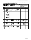
. A complete Parts List is available at www.MillerWelds.com
OM-4419 Page 27
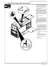
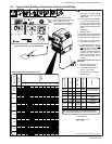
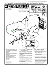
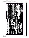
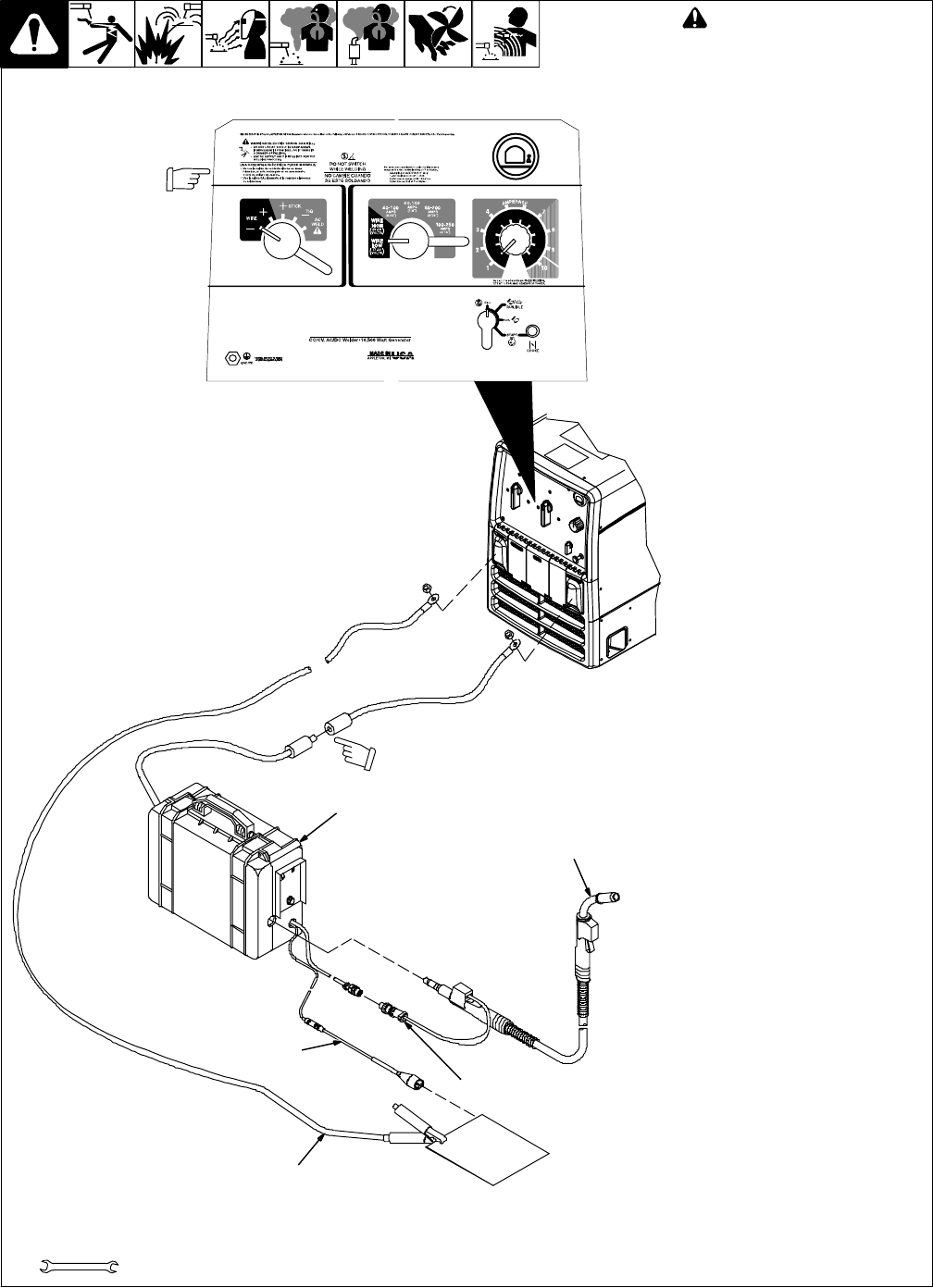
B. Self-Shielded Flux Core Wire Applications
803 750-B / 802 766 / 228 201-B
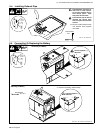
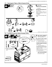
! Stop engine.
. This section provides general
guidelines and may not suit all
applications.
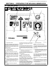
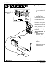
. The control panel shows the typi-
cal settings for welding with .045
(71T-11) self-shielded flux core
wire.
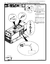
1 Work Clamp
2 Wire Feeder
3 MIG Gun
4 Gun Trigger Plug
5 Voltage Sensing Clamp
Connect work cable to welding gen-
erator Work terminal. Connect cable
from wire feeder to cable from weld-
ing generator Electrode terminal.
. Be sure to use the correct size
weld cables (see Section 5-7).
Loosen MIG gun securing knob. In-
sert gun end through opening in feed-
er and position as close as possible
to drive rolls without touching. Tight-
en knob.
See wire feeder manual for wire
threading procedure.
Insert gun trigger plug (item 4) into
matching receptacle and tighten
threaded collar.
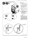
Typical Control Settings Using
.045 (71T-11) Self-Shielded Flux
Core Wire :
> Set Weld Process Selector
switch to Wire − position
(DCEN).
> Set Coarse Range switch to
Wire/Low Range (17-22 volts)
position.
> Set Fine Control near minimum
setting.
> Set wire feed speed between
125-200 ipm.
> Do a test weld. To increase arc
length, increase Fine Control
setting. To shorten arc length,
reduce fine control setting or in-
crease wire feed speed.
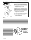
Tools Needed:
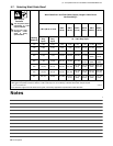
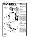
Typical Control Settings For .045 (71T-11) Self-Shielded Flux Core Wire
3/4 in
Note Coarse Range,
Fine Control, and
Weld Process switch
settings.
Quick connector
3
2
5
1
4
Work