


OM-193 267 Page 18
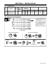
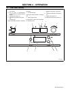
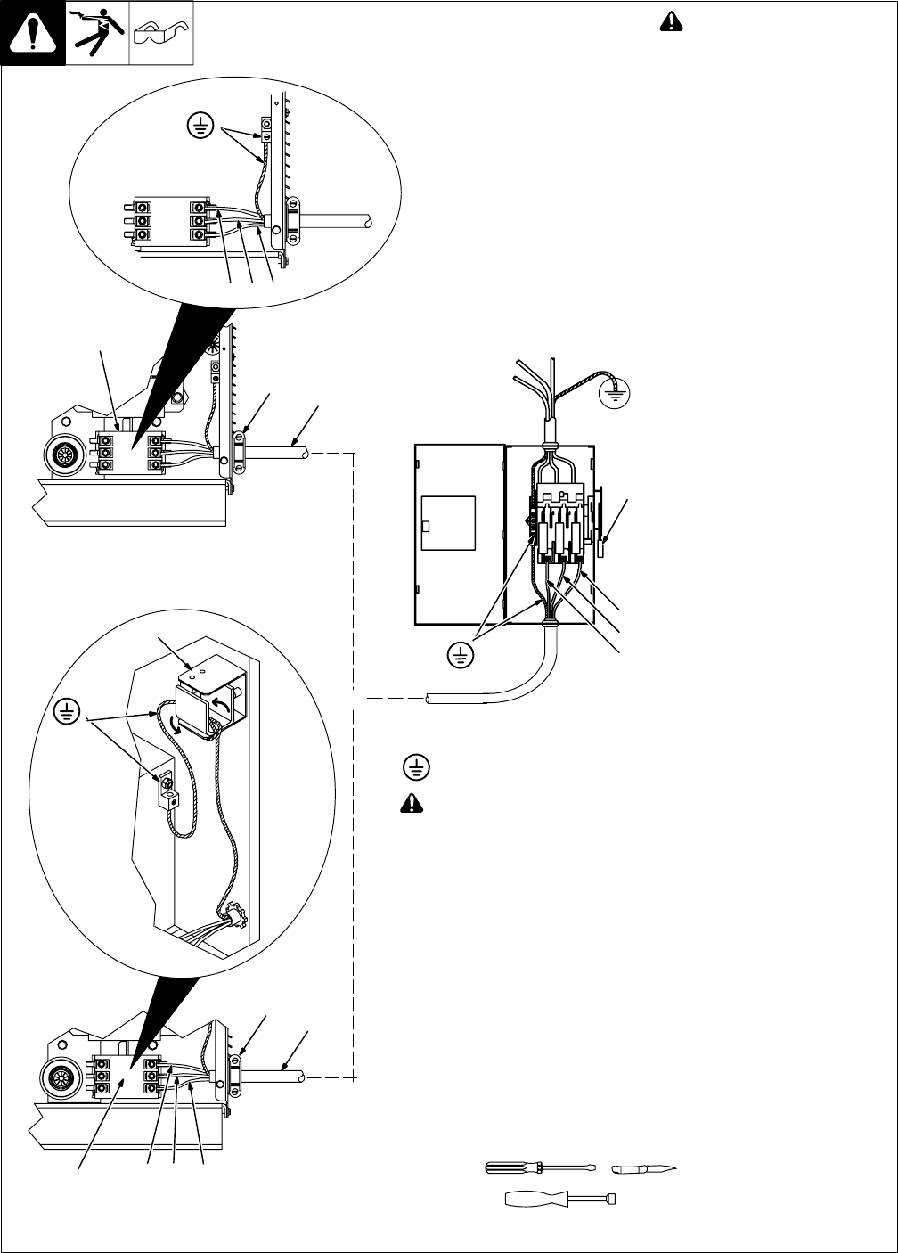
3-12. Connecting Input Power
801 535-B / 801 822-A
! Turn Off welding power
source, and check voltage
on input capacitors accord-
ing to Section 6-3 before
proceeding.
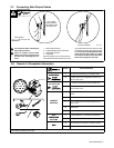
1 Strain Relief Connector Clamp
Obtain and install proper connector.
2 Input And Grounding
Conductors
3 Contactor W1
Select size and length using Sec-
tion 3-10. Connect as shown in
illustration.
For Models With Optional
Ground Current Sensor:
4 Ground Current Sensor
When cutting input and ground con-
ductors to length, ground conductor
must be 26 inches (660 mm) long to
wrap around ground current sen-
sor. Note that ground conductor
must be insulated between strain
relief and ground terminal.
Insert input and grounding conduc-
tors through strain relief. Route
grounding conductor through reed
switch from right side of unit, under
switch, and through reed switch
again (two turns total) before con-
necting to ground terminal.
For All Models:
5 Line Disconnect Device
See Section 3-10.
Reinstall right side panel.
Tools Needed:
5/16 in
L1 L2 L3
= GND/PE
! Always connect grounding
conductor first.
L1
5
L2
L3
2
Or
Connections For
Standard Model
Connections For
Models With Optional
Ground Current Sensor
2
1
1
L1
L3
L2
3
4
3