


OM-218 Page 12
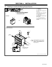
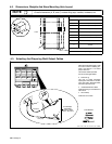
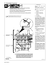
4-2. Dimensions, Weights And Base Mounting Hole Layout
Overall dimensions (A, B, and C) include lifting eye, handles, hardware, etc.
NOTE
Dimensions
A 77-1/4 in (1943 mm)
B 72 in (1829 mm)
H
A
C 40 in (1016 mm)
C
D 52-1/2 in (1334 mm)
D
Front
B
C
E 3/4 in (19 mm)
F 38-1/2 in (978 mm)
G
G 26-1/4 in (667 mm)
H 36 in (914 mm)
J
1/2 in Dia. (13 mm Dia.)
4 Holes
E
F
J
R f ST 144 567 A
Weight
Ref. ST-144 567-A
4050 lb (1837 kg)
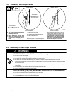
sb6.1* 5/94 − Ref. ST-144 570-A / Ref. S-0653
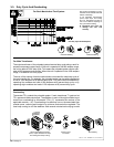
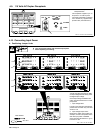
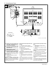
1 Weld Output Cable
Determine total cable length in weld
circuit and maximum welding am-
peres. Use Section 4-4 to select
proper cable size.
Use shortest cables possible.
Do not use damaged cables.
2 Terminal Lug
Use lugs of proper amperage
capacity and hole size for connect-
ing to work clamp, electrode holder,
and weld output terminals.
3 Insulated Electrode Holder
Install according to manufacturer’s
instructions.
4 Work Clamp
Install onto work cable.
Tools Needed:
10 ft (3 m)
1
Total Cable
Length In Weld
Circuit = 20 ft (6 m)
10 ft (3 m)
For Example,
2
4
3
2
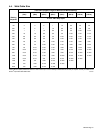
4-3. Selecting And Preparing Weld Output Cables