


OM-218 Page 23
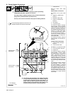
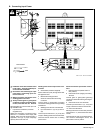
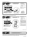
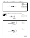
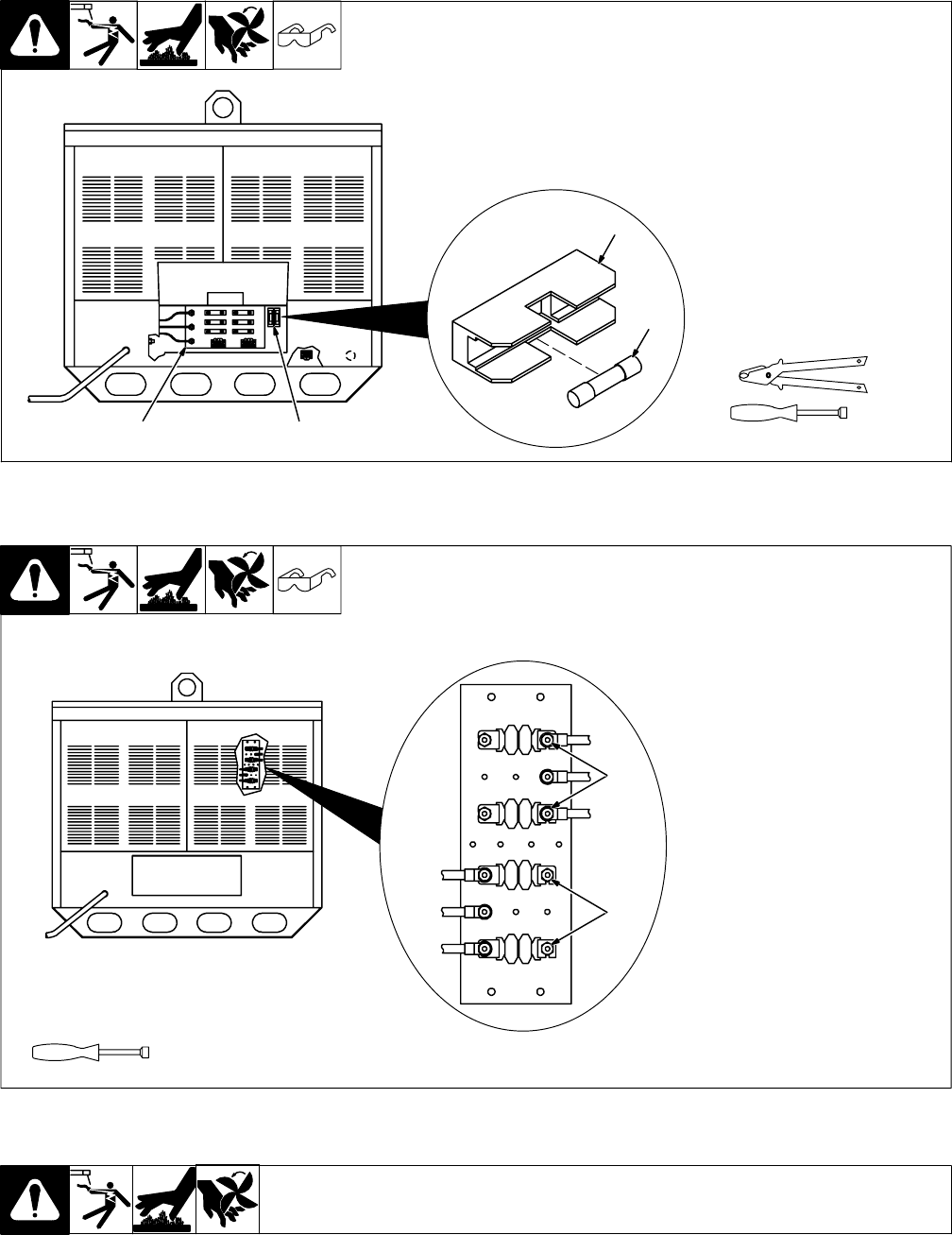
B. Control Fuses F3 And F4
Ref. ST-144 569-B / Ref. ST-146 126-C
Turn Off polyweld system and dis-
connect input power.
1 Input Terminal Board
2 Fuses F3 And F4 Location
3 Fuse F3 Or F4 (See Parts List
For Rating)
4 Fuse Holder
Check F3 or F4, and replace if
needed. Use proper tool when re-
moving fuse.
Close rear access door.
Tools Needed:
3/8 in
4
3
12
Y Turn Off polyweld system, and dis-
connect input power before inspect-
ing, maintaining, or servicing.
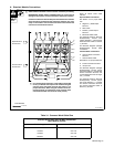
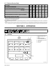
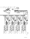
C. Module Fuse Links F11 And F12 Through F81 And F82
ST-800 479 / ST-155 300
Turn Off polyweld system and dis-
connect input power.
1 Fuse Links (Odd Number
Modules)
2 Fuse Links (Even Number
Modules)
Each of the eight modules is pro-
tected from overload by a pair of
link-type fuses FX1 and FX2 (“X”
represents the number of the appli-
cable module, 1−8). If one fuse link
for a module opens, low weld output
is available at the applicable mod-
ule. If both fuse links open, no weld
output is available at the affected
module.
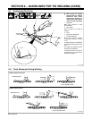
To replace fuse(s), proceed as
follows: Remove upper rear panel.
Check fuse(s), and replace if nec-
essary. Reinstall upper rear panel.
1
2
Tools Needed:
3/8, 1/2 in
Y Turn Off polyweld system, and discon-
nect input power before inspecting,
maintaining, or servicing.
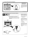
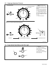
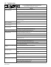
6-3. Blank Module Panel
Y Turn Off polyweld system, and disconnect input power
before inspecting, maintaining, or servicing.
A blank module panel is included with each polyweld system. If a module is removed, install the blank module panel in
the location where the module was removed before using the remaining modules. This panel prevents the touching of
inside parts and wires, and ensures proper air flow through the polyweld system.