


OM-218 Page 16
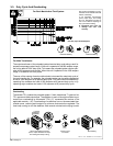
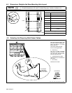
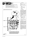
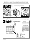
B. Parallel Module Connections
1 Cable Restraint
Route all cables under cable
restraint.
Separate Work Connections
See Section 4-4 for proper cable
size.
2 Negative (−) Weld Output
Terminal
3 Electrode Holder Cable
4 Positive (+) Weld Output
Terminal
5 Work Cable
6 Connection Point
For Electrode Negative (Straight
Polarity/DCEN), connect separate
cables of same size and length from
Positive (+) terminals to the work or
to a suitable connection point con-
necting to a single work cable.
Connect separate cables of same
size and length from Negative (−)
terminals to a suitable connection
point connecting to a single elec-
trode holder cable.
For Electrode Positive (Reverse
Polarity/DCEP), reverse cable con-
nections.
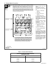
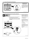
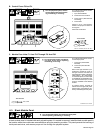
Common Work Connections
7 Common Work Connection
Terminal
8 Common Work Cable
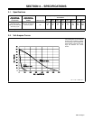
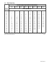
See Table 3-1 for proper size cable.
9 Frame Connection Terminal
10 Jumper Link
For Electrode Negative (Straight
Polarity/DCEN), connect jumper
link across Positive (+) terminal and
Frame Connection terminal for
each paralleled module. Connect
separate cables of same size and
length from Negative (−) terminals
to a suitable connection point con-
necting to a single electrode holder
cable.
For Electrode Positive (Reverse
Polarity/DCEP), connect jumper
link across Negative (−) terminal
and Frame Connection terminal for
each paralleled module, and con-
nect separate cables of same size
and length from Positive (+) termi-
nals to a suitable connection point
connecting to a single electrode
holder cable.
ST-085 152-D
Securely cover con-
nection with proper
insulating material.
7
8
3
4
9
10
3
6
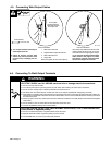
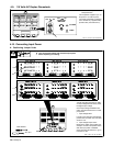
Tools Needed:
1-1/4 in
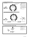
Set the Amperage Adjustment controls on all
paralleled modules to provide the same output.
Separate Work
Connections
Common Work
Connections
1
2
5
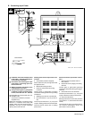
Y READ SAFETY BLOCKS at start of Section 4-6 before proceeding.
UNDERSIZED WELDING CABLES can cause fire.
Use single cables of adequate capacity to carry the total combined am-
perage of the paralleled modules (see Section 4-4) .
Securely cover common connections with proper insulating materials.
Y For common work connection, work cable must be able
to carry combined weld output of all modules using the
common work connection terminal (see Table 3-1 for
proper cable size). When using the common work con-
nection terminal, all connections to the common work
connection terminal must be of the same polarity.