


17OM-402
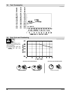
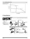
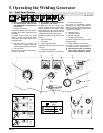
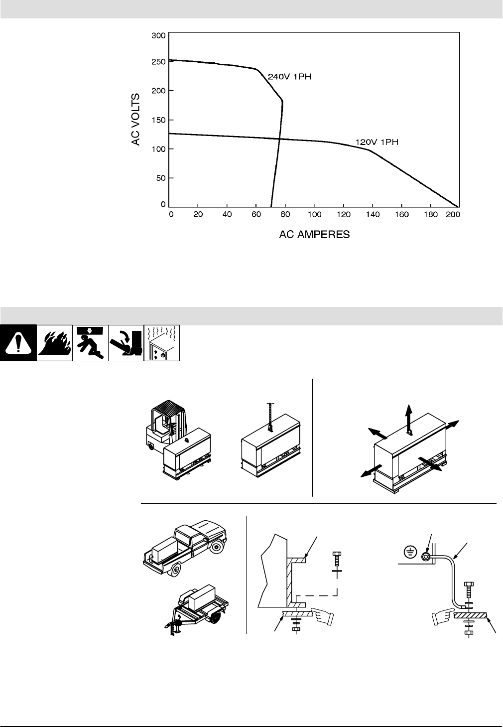
3.6 AC Auxiliary Power Curve
SA-180 260
The auxiliary power curve shows
the auxiliary power in amperes
available at the receptacles.
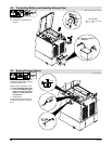
4. Installation
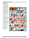
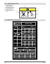
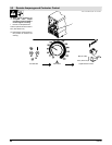
4.1 Installing Welding Generator
install1 1/97 − Ref. ST-800 652 / Ref. ST-800 477-A / ST-158 936-A / S-0854
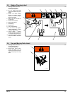
1 Generator Base
2 Metal Vehicle Frame
3 Equipment Grounding
Terminal
4 Grounding Cable
Use #10 AWG or larger insulated
copper wire.
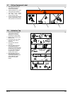
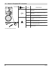
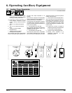
Y If unit does not have GFCI re-
ceptacles, use GFCI-
protected extension cord.
1
2
Electrically bond genera-
tor frame to vehicle frame
by metal-to-metal contact.
GND/PE
3
4
2
OR
OR
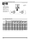
18 in
(460 mm)
18 in
(460 mm)
18 in
(460 mm)
18 in
(460 mm)
18 in
(460 mm)
OR
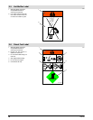
Movement Airflow Clearance
Location
Grounding
Y Do not lift unit from end.