


30 OM-402
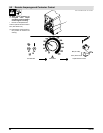
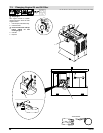
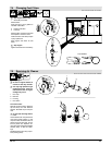
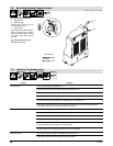
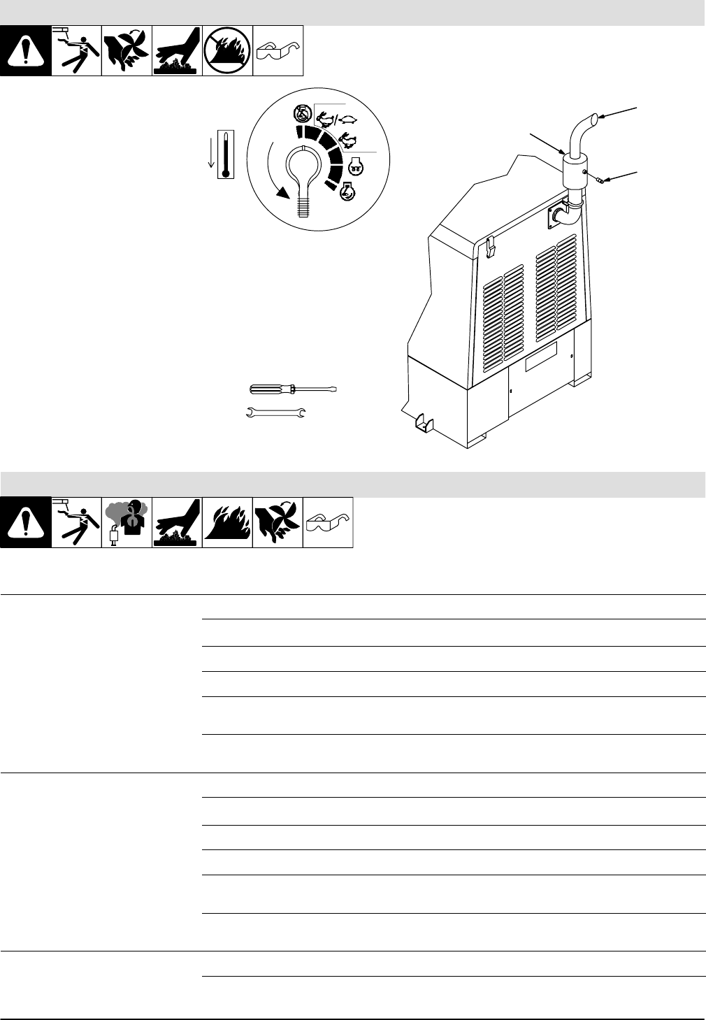
7.8 Servicing Optional Spark Arrestor
ST-801 154-B / Ref. ST-175 918-C
Y Stop engine and let cool.
1 Spark Arrestor
2 Cleanout Plug
Remove plug and remove any dirt
covering cleanout hole.
3 Exhaust Pipe
Start engine and run at idle speed to
blow out cleanout hole. If nothing
blows out of hole, briefly cover end
of exhaust pipe with fireproof
material.
Y Stop engine and let cool.
Reinstall cleanout plug.
1
3/8 in
Tools Needed:
2
3
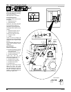
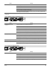
7.9 Welding Troubleshooting
Trouble Remedy
No weld output. Check control settings (see Section 5.1).
Check fuses F2 and F3, and replace if necessary (see Section 7.7).
Have Factory Authorized Service Agent check main rectifier and capacitor C5.
Check and secure connections to Remote 14 Receptacle RC1.
Place Output (Contactor) Control switch in On position, or place switch in Remote 14 position and
connect remote contactor to Remote 14 receptacle RC1 (See Section 5.1).
Have Factory Authorized Service Agent check brushes and slip rings, main rectifier, integrated
rectifier SR3, capacitor C5, and circuit boards PC1 and PC6.
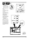
Low weld output. Check control settings (see Section 5.1).
Check fuses F2 and F3, and replace if open (see Section 7.7).
Check engine speed, and adjust if necessary (see Section 7.6).
Tune engine according to engine manual.
Place Amperage Control switch in Panel position, or place switch in Remote 14 position and connect
remote amperage control to Remote 14 receptacle RC1.
Have Factory Authorized Service Agent check brushes and slip rings, main rectifier, integrated rectifi-
er SR3, capacitor C5, Amperage Control R4, and circuit board PC6.
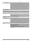
High weld output. Check engine speed, and adjust if necessary (see Section 7.6).
Have Factory Authorized Service Agent check main rectifier.