


19OM-402
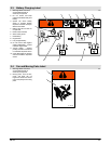
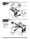
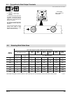
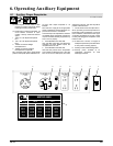
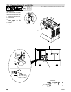
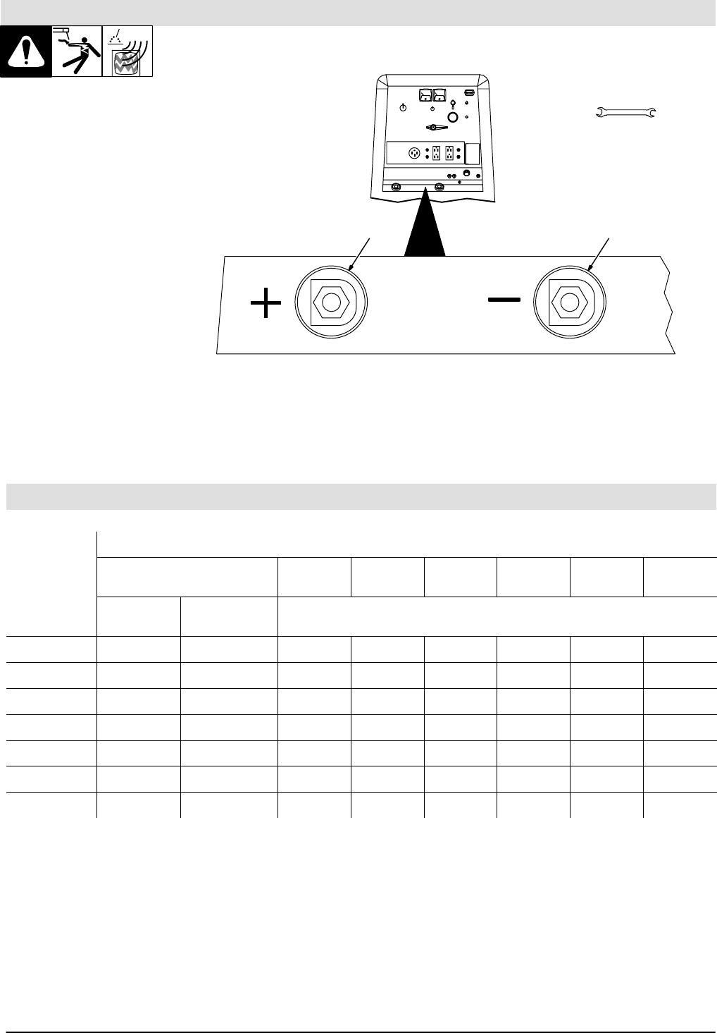
4.4 Connecting to Weld Output Terminals
Ref. ST-158 936-D / Ref. ST-175 918-C
1 Positive (+) Weld Output
Terminal
2 Negative (−) Weld Output
Terminal
For Direct Current Electrode Positi-
ve (DCEP), connect work cable to
Negative (−) terminal and electrode
cable (Stick) or torch cable (TIG) to
Positive (+) terminal.
For Direct Current Electrode Nega-
tive (DCEN), reverse cable con-
nections.
If unit has optional polarity switch,
connect work cable to Work
terminal and electrode or torch
cable to electrode terminal.
Tools Needed:
3/4 in
1 2
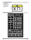
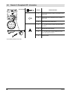
4.5 Selecting Weld Cable Sizes
Total Cable (Copper) Length in Weld Circuit Not Exceeding
Welding
Amperes
100 ft (30 m) or Less
150 ft
(45 m)
200 ft
(60 m)
250 ft
(70 m)
300 ft
(90 m)
350 ft
(105 m)
400 ft
(120 m)
Amperes
10 − 60%
Duty Cycle
60 − 100% Duty
Cycle
10 − 100% Duty Cycle
100 4 4 4 3 2 1 1/0 1/0
150 3 3 2 1 1/0 2/0 3/0 3/0
200 3 2 1 1/0 2/0 3/0 4/0 4/0
250 2 1 1/0 2/0 3/0 4/0 2-2/0 2-2/0
300 1 1/0 2/0 3/0 4/0 2-2/0 2-3/0 2-3/0
350 1/0 2/0 3/0 4/0 2-2/0 2-3/0 2-3/0 2-4/0
400 1/0 2/0 3/0 4/0 2-2/0 2-3/0 2-4/0 2-4/0
Weld cable size (AWG) is based on either a 4 volts or less drop or a current density of at least 300 circular mils per ampere. S-0007-D