


OM-4411 Page 23
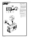
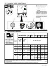
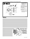
6-2. Description Of Front Panel Controls
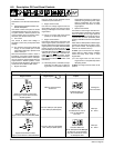
1 Process Switch
See Section 6-3 for Process switch informa-
tion.
2 Voltage/Amperage Adjust Switch And
Remote Receptacle
Use switch to select front panel or remote
voltage/amperage control. For remote con-
trol, place switch in Remote position and
connect remote control to Remote recep-
tacle RC4 (see Sections 5-8 and 6-4).
3 V/A Control
Use control to select weld voltage or
amperage. Control may be adjusted while
welding.
. For maximum weld output (above 220
Amps), run unit at 3600 rpm. For weld
output below 220 Amps, operate unit at
3000 or 3600 rpm.
With Process/Contactor switch in Stick or
TIG setting, use control to adjust amperage.
With Process/Contactor switch in Wire posi-
tion, use control to adjust voltage. With V/A
Adjust Switch in Remote position, control
limits the remote amperage in Stick and TIG
modes, but has no effect in MIG modes.
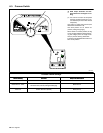
4 Engine Hour Meter
Use hour meter to help schedule routine
maintenance (see Section 8-1).
5 Engine Choke Control
Use control to change engine air-fuel mix
when starting engine. Pull control out when
starting a cold engine. Push control in when
engine starts.
. Do not run engine with Choke control
partially on or spark plugs will foul.
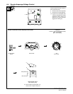
6 Engine Control Switch
Use switch to start engine, stop engine, and
select engine speed. (Use switch in com-
bination with Speed Control switch to select
engine speed.) In Run/Idle 3600/2400 RPM
position, engine runs at 2400 rpm at no weld
load, and 3600 rpm under weld load. In Run/
Idle 3000/1800 RPM position, engine runs at
1800 rpm at no weld load, and 3000 rpm
under weld load. In either position, engine
speed is determined by weld load and posi-
tion of Speed Control switch (see item 7 and
table below).
. Generator power is available at recep-
tacles RC1 and RC2 only at 1800 rpm.
If generator is not locked at 1800 rpm,
engine speed increases in response to
weld load and generator power output
stops at receptacles RC1 and RC2.
Generator power load does not affect
engine speed.
7 Speed Control Switch
Use switch to control engine auto idle func-
tion. Place switch in Generator Lock position
when not welding to lock engine speed at
1800 rpm for generator power at 60 Hz ac re-
ceptacles RC1 and RC2. (Generator power
is always available at 60-120 Hz receptacle
RC3.)
Place switch in Weld position to allow engine
speeds to be determined by position of En-
gine Control switch. The Speed Control
switch is not needed at start-up.
To Start: pull out choke and turn Engine
Control switch to Start position. Release
switch and slowly push choke in when
engine starts.
. If the engine does not start, let the
engine come to a complete stop before
attempting restart.
To Stop: turn Engine Control switch to Off
position.
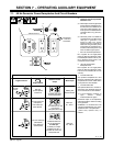
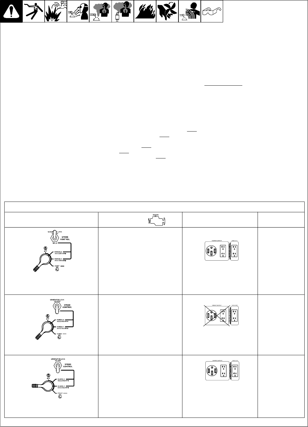
Controlling Engine Speed And Weld/Generator Power Output
1800 rpm (Power Speed)
Continuous
No Load: 2400 rpm (Idle Speed)
Load: 3600 rpm (Weld Speed)
Engine Controls
Engine Speed
Generator Power
Output
Weld Output
5 kW/kVA Total From
All AC Receptacles
2.4 kW/kVA at 60-120 Hz
From AC Receptacle
RC3 Only
No Load: 1800 rpm (Idle Speed)
Load: 3000 rpm (Weld Speed)
Welding Not
Recommended
3600 rpm:
20 − 300 A
3000 rpm:
20 − 220 A
Speed Control Switch In Generator
Lock. Engine Control Switch in either
Run/Idle position.
Speed Control Switch In Weld.
Engine Control Switch in 3600/2400 RPM.
Speed Control Switch In Weld.
Engine Control Switch in 3000/1800 RPM.
5 kW/kVA Total From
All AC Receptacles At 1800 rpm.
At 3000 rpm, Output Available
Only At 2.4 kW/kVA 60-120 Hz
AC Receptacle RC3