


OM-4411 Page 35
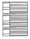
Trouble Remedy
Lack of high frequency; difficulty in
establishing Gas Tungsten Arc Weld-
ing arc.
Use proper size tungsten for welding amperage.
Reduce leakage of high frequency from torch or work cable (check grounding, remove excessive
coils from weld cables, use shorter weld cables, etc.).
Check cables and torch for cracked or deteriorated insulation or bad connections. Repair or replace
necessary parts.
Wandering arc − poor control of arc
direction.
Reduce gas flow rate.
Select proper size tungsten. Properly prepare tungsten.
Tungsten electrode oxidizing and not
remaining bright after conclusion of
weld.
Shield weld zone from drafts.
Increase postflow time.
Check and tighten all gas fittings.
Properly prepare tungsten.
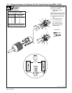
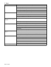
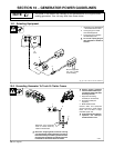
B. 60 Hz Generator Power Receptacles RC1 And RC2
Trouble Remedy
No power output at 60 Hz ac recep-
tacles RC1 or RC2.
Reset circuit breakers CB1 and/or CB3 (see Section 7-1).
Stop welding, or place Speed Control switch in Generator Lock position to run engine at 1800 rpm. 60
Hz receptacles RC1 and RC2 work only at 1800 rpm.
Check receptacle wiring and connections.
Check fuse F1 on circuit board PC7, and replace if necessary (see Section 8-6).
Have Factory Authorized Service Agent check brushes, slip rings, and circuit boards PC1, PC2, and
PC7.
Low power output at 60 Hz ac recep-
tacles RC1 or RC2.
Check and clean air cleaner as necessary.
Check engine electronic governor system. See engine manual.
High power output at 60 Hz ac recep-
tacles RC1 or RC2.
Check engine electronic governor system. See engine manual.
Erratic power output at 60 Hz ac
receptacles RC1 or RC2.
Have Factory Authorized Service Agent check brushes, slip rings, and circuit boards PC1, PC2, and
PC7.
Check receptacle wiring and connections.
Check governor according to engine manual.
C. Variable Frequency Generator Power Receptacle RC3
Trouble Remedy
No generator power output at ac re-
ceptacle RC3.
Reset circuit breaker CB4 (see Section 7-2).
Check receptacle RC3 for continuity and proper connections. Replace receptacle if necessary.
Check fuse F1 on circuit board PC7 and replace if necessary (see Section 8-6).
Have Factory Authorized Service Agent check brushes and slip rings, and circuit boards PC1, PC2, and
PC7.
Low generator power output at ac re-
ceptacle RC3.
Check fuse F1 on circuit board PC7 and replace if necessary (see Section 8-6).
Turn Engine Control switch to Run/Idle 3600/2400 RPM position.