


OM-1589 Page 12
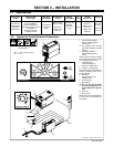
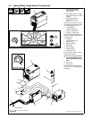
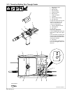
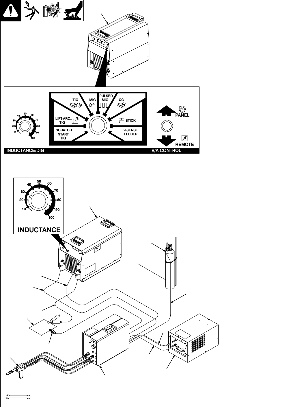
3-3. Typical Water-Cooled System Connections
801 810 / Ref. 175 086 / Ref. 180 311-B
1 300/400 Ampere Model
CC/CV Inverter Welding
Power Source
. Use settings shown for both
pulse MIG welding and MIG
welding.
2 450 Ampere Model CV
Inverter Welding Power
Source
System can be set up with a variety
of conventional Constant Voltage
(CV) welding power sources.
3 14-Pin Plug And
Interconnecting Cord
4 Positive (+) Weld Cable
5 Negative (−) Weld Cable
Select and prepare weld cables ac-
cording to welding power source
Owner’s Manual.
6 Workpiece
7 Voltage Sensing Lead
(Optional Use)
8 Water-Cooled Gun
9 Wire Feeder
10 Coolant Supply
11 Coolant In Hose
12 Coolant Out Hose
Connect hoses between coolant
supply and wire feeder.
Y Do not use gas pressure
above 50 psi (345 kPa) or me-
chanical gas valve in gun can
leak.
13 Gas Hose
14 Gas Cylinder
Route hose from regulator/flowme-
ter and connect to shielding gas
valve fitting.
Tools Needed:
9/16, 5/8, 11/16, 3/4 in
1
2
3
4
5
6
7
8
9
14
13
10
11
12