


OM-1589 Page 22
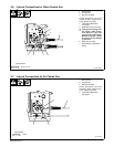
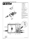
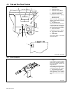
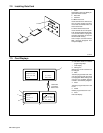
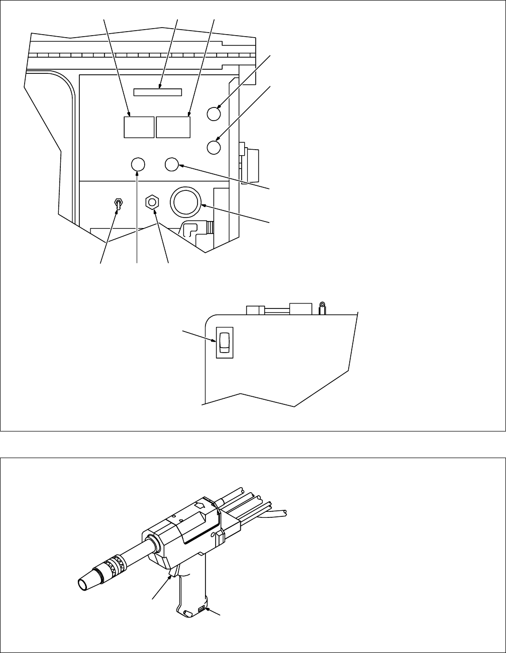
4-4. Side and Rear Panel Controls
Ref. 800 690-A / Ref. 800 869
1 Mode Display
2 Data Card Slot
3 Parameter Display
4 Parameter Increase Button
5 Parameter Decrease Button
6 Parameter Select Button
Press button to move > in display.
7 Optional Gas Flow
Adjustment Knob
Allows accurately presetting gas
flow rate on wire feeder front panel
digital display.
8 Circuit Breaker CB1
CB1 protects the wire feeder from
overload. If CB1 trips, the wire feed-
er shuts down. Allow a cooling peri-
od and manually reset the breaker.
9 Mode Select Button
Press button to move > in display.
10 Torque Switch (See Section
3-11)
11 Power Switch
Use Power switch to turn wire
feeder On and Off.
1 23
4
5
6
7
10 9 8
11
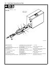
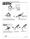
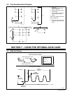
4-5. Gun Controls
Ref. 800 939
1 Trigger
Press trigger to energize welding
power source contactor (if applica-
ble), start shielding gas flow, and
begin wire feed.
For shielding gas preflow and post-
flow, partially press trigger before
and partially release after welding.
2 Increase/Decrease Switch
Use switch to adjust value of se-
lected parameter. The numbers
around the control are for reference
only.
1
2