


OM-492 Page 25
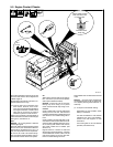
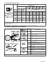
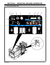
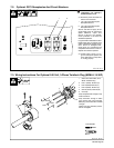
6-2. Description Of Controls (See Section 6-1)
. The fan motor is thermostatically
controlled and only runs when cooling is
needed.
Engine Lights
1 Engine Temperature Light
Light goes on and engine stops if engine tem-
perature is too high.
NOTICE − Stop engine and fix trouble if En-
gine Temperature light goes on.
2 Engine Oil Pressure Light
Light goes on and engine stops if oil pressure
is too low. Light goes on momentarily during
start-up but goes out when engine reaches
normal oil pressure.
NOTICE − Stop engine and fix trouble if En-
gine Oil Pressure light stays on after start-up.
3 Battery Charging Light
Light goes on if engine alternator is not charg-
ing battery. Engine continues to run.
NOTICE − Stop engine and fix trouble if Bat-
tery Charging light goes on.
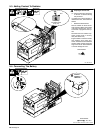
Engine Gauges
4 Engine Hour Meter
Use hour meter to help schedule routine main-
tenance.
5 Fuel Gauge
Weld Controls
6 Dig/Inductance Control
Control adjusts Dig when Stick mode is se-
lected on mode switch. When control is set to-
ward minimum, short-circuit amperage at low
arc voltage is the same as normal welding
amperage.
When set toward maximum, short-circuit am-
perage is increased at low arc voltage to as-
sist with arc starts and help prevent the elec-
trode from sticking while welding (see volt-am-
pere curves in Section 4-4).
Select setting best suited for application.
Control adjusts inductance when MIG or
V-Sense Feeder position is selected on the
mode switch. Inductance determines the
“wetness” of the weld puddle. When set to-
ward maximum, “wetness” (puddle fluidity) in-
creases.
Control is not functional when Pulsed MIG or
one of the TIG modes is selected.
7 Voltmeter
Meter displays weld voltage and help mes-
sages (see Sections 6-3 and 8-10).
8 Ammeter
Meter displays weld amperage and help mes-
sages (see Sections 6-3 and 8-10).
9 V/A (Voltage/Amperage) Adjustment
Control
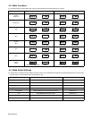
10 Mode Switch
The Mode switch setting determines both the
process and output On/Off control (see Sec-
tion 6-4). Source of control (panel or remote)
for the amount of output is selected by the V/A
Control switch.
For Air Carbon Arc (CAC-A) cutting and goug-
ing, place switch in Stick position. For best re-
sults, place Dig/Inductance control in the max-
imum position.
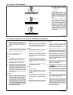
11 V/A (Voltage/Amperage) Control Switch
And Remote 14 Receptacle
For front panel control, place switch in Panel
position and use the V/A Adjustment control.
For remote control, make connections to Re-
mote 14 receptacle (see Section 5-8), and
place switch in Remote position. In most
modes, remote control is a percent of V/A Ad-
justment control setting (value selected on
V/A Adjustment control is maximum available
on remote). In the MIG mode, remote control
provides full range of unit output regardless of
V/A Adjust control setting.
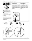
Engine Starting Controls
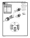
12 Glow Plug Switch
Use switch to energize glow plugs for cold
weather starting. Glow plugs warm in about
six seconds and engine can be started (see
starting instructions following).
NOTICE − Do not use glow plug longer than
20 seconds.
13 Engine Control Switch
Use switch to start engine, select speed, and
stop engine. In Run/Idle position, engine runs
at idle speed at no load, and weld/power
speed under load. In Run position, engine
runs at weld/power speed.
To Start:
NOTICE − Do not use ether as a starting aid.
Using ether voids warranty.
Above 325 F: turn Engine Control switch to
Start. Release switch when engine starts and
Engine Oil Pressure light goes out.
. If engine does not start, let engine come
to a complete stop before attempting re-
start.
Below 325 F: turn engine control switch to
Run/Idle position. Push Glow Plug switch up
and hold about six seconds. Turn Engine Con-
trol switch to Start. Release switch when en-
gine starts and Engine Oil Pressure light goes
out.
See Section 6-6 for additional information on
cold weather operation.
. If engine does not start, let engine come
to a complete stop before attempting re-
start.
To Stop: turn Engine Control switch to Off
position.
. Push engine stop lever to stop engine if
Engine Control switch does not work (see
item 14).
14 Engine Stop Lever
Use lever to stop engine if Engine Control
switch does not work.